Abstract: Design a low frame rate wireless video transmission system to transmit images on the screen of a personal computer to the projector wirelessly. In the system, the video transmitting end adopts an ordinary personal computer, and the video receiving end is an embedded system based on ARM11. The transmitted image is compressed using the JPEG standard, and the transmission data link is Wi-Fi. The system is mainly used for teaching, conferences and other occasions. This system can reduce the cable in the demonstration occasion and save the trouble of frequent insertion and removal. This article refers to the address: http:// StormPorto Service
Unlike other suppliers,we accept your job with multiple designs in one panel.Many customers told us they would like to cut cost when they are doing design jobs as the first prototypes may change in next version .Only 1 or 2 units they need for each design.So,our StormProto helps. it includes
.Express 2-3 working days
.Two panel size:270*420mm,370*420mm
Prototype PCB,2 Layer Eing Board,Supply Board PCB,Black Prototype PCB Storm Circuit Technology Ltd , http://www.stormpcb.com
Keywords: wireless video transmission; ARM; embedded system; Linux
The wirelessization of personal computer equipment and its peripherals has always been an industry trend. With the advancement of technology, wireless devices such as wireless mice, wireless keyboards, and wireless routers have come out. However, almost all projectors currently in use are connected by cables and computers, which is often inconvenient in business or scientific research meetings or exhibitions.
Video transmission has a large amount of data and high real-time requirements. To complete wireless video transmission, the data throughput of the wireless link must be greater than the video data traffic. In recent years, the Wi-Fi standard has been evolving and the transmission speed is getting higher and higher. On the other hand, the processing power of the embedded processor is getting stronger and stronger, and the chip manufacturer will integrate the DSP core in some embedded processors to make the embedding. The video decoding capability of the system has been greatly improved, and high-resolution video decoding can be completely completed, which makes it possible to transmit compressed video data, thereby indirectly reducing the bandwidth occupied by the video data stream. All of this makes wireless video transmission possible.
1 system hardware composition
1.1 System overall framework The system consists of a video sender and a video receiver, with Wi-Fi as the communication link between them. As shown in Figure 1, the video sending end is an ordinary computer that needs to play a slide show. The video receiving end is an embedded system using an ARM11 processor. It is responsible for receiving and decoding video signals, and transmitting video signals to the large through the VGA interface. The screen displays on the device (such as a projector, large flat panel TV, etc.). 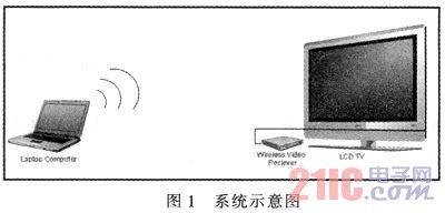
1.2 The hardware structure of the video receiving end The image receiving end adopts the embedded system based on Samsung S3C6410 chip. The S3C6410 chip uses a 65 nm process with a maximum frequency of 667MHz. The internal use of ARM11 core as the main control part, and integrated memory controller, USB controller, LCD controller and other external device control, interface; at the same time, S3C6410 also integrated Multimedia Acceleration (Multimedia Acceleration). The S3C6410 chip is shown in Figure 2. 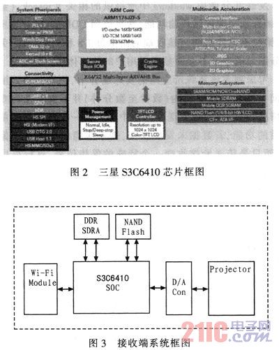
The multimedia processing core integrated in the chip includes a JPEG codec, which can realize hardware decoding of JPEG format pictures, thereby greatly improving the system's ability to process JPEG pictures. It supports up to 65 535x65 535 resolution JPEG images. The receiving system block diagram is shown in Figure 3.
The video receiver is equipped with a Marvell 8636-based Wi-Fi module that supports the 802.11b/g standard and is connected to the system via the SDIO interface.
The video data is decompressed and output to the digital-to-analog conversion module, and finally converted to a VGA signal and sent to the projector.
2 system software design
2.1 System Software Box The main functions of the video sender software: collecting the current screen display image, compressing the image, and transmitting the compressed image. In addition to this, the sender software also needs to complete the setup and disconnection functions of the connection with the receiver. Correspondingly, the main function of the receiving end software is to receive the compressed image data, decode the image, and display the image. Data is transmitted between the sender and the receiver over the Wi-Fi link. The system software architecture block diagram is shown in Figure 4. 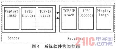
In conference situations, the typical presentation is to play a slideshow. In this application, the image is quasi-static most of the time, so in this case the video refresh rate can be kept at a lower value. Above, here we set it to 8 frames per second. At this time, if the screen resolution of the computer is 1 280×800 and the color depth is 24 bits, the video stream rate is 197 Mb/s.
The currently widely adopted 802.11 g Wi-Fi standard, which has a nominal speed of only 54 Mbps, does not meet the data bandwidth required above. So you need to compress the data. At a resolution of 1 280x800, the compression ratio needs to be above 5:1, and the JPEG standard can be considered. The JPEG compression quality comparison is shown in Figure 5. 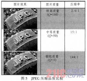
JPEG is a very flexible coding standard, and its Q value can be arbitrarily selected within 100. However, if the picture quality is too high, it not only increases the burden on the CPU when the image is encoded, but also increases the amount of data transmission; and the picture quality is too low, which will affect the quality of the presentation. Need to find a balance between image quality and data traffic.
Figure 5 is a comparison of the effects of pictures under different JPEG encoding quality. When Q is taken as 50, the compressed image still has a higher image quality under the naked eye. At this time, the compression ratio is 15:1, which is greater than the 5:1 compression ratio requirement proposed in the previous analysis. In this case, the data rate is 13 Mb/s, which can be transmitted under the bandwidth provided by 802.11 g. It can be seen that when Q=50, a good balance can be obtained between image quality and data flow.
2.2 Video sender software design The system's sender software is based on windows design. The main functions of its implementation can be summarized as: collecting the current screen display image, compressing the image, and transmitting the compressed image. The sender software flow chart is shown in Figure 6. 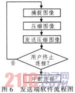
The methods for capturing the current screen in the Windows environment are: GDI, DirectX, and Windows Media API. The use of GDI is not efficient and is not suitable for use in this system. DirectX is used here.
The g_pd3dDevice object is provided in DirectX. This is an IDixeet3DDevice9 object. You can call the IDirect3DSudace9::LockRect() method to get a pointer to the first address of the current display cache, and then use the appropriate algorithm to calculate the current display buffer. Size, you can easily copy the contents of the display cache to the specified memory area, and use the JEPG standard to compress the collected data. The specific principles and processes are as follows: Each DirectX program includes a background cache. At the same time, each program can access the foreground cache in the default state, and the foreground cache stores the current Windows desktop content. Accessing this foreground cache captures the image displayed on the current desktop. Here are the key codes to capture the screen.
In the following code snippet, g_pd3dDevice is an IDirect3D Device9 object, assuming it has been initialized. This code captures the desired desktop image and then processes the captured bitmap. At this point you can call the IDirect3DSurface9::LockRect() method to get a pointer to the first byte of the captured bitmap, then determine the size of the bitmap according to the size of the screen, and finally copy the required bitmap data. Go to the cache defined in advance. 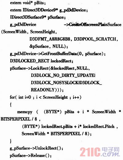
It should be noted that the bitmap captured in the above code does not necessarily have the width of the actual width of the screen. This is because the memory alignment method is used when storing the bitmap. The memory is typed in the bitmap. Word) aligns, so at the end of each line you may need to add extra bytes to complete the memory, so that the bitmap width is larger than the actual screen width. At this point you can use lockedRect. Pitch to get the actual width of each line.
The double buffer mode is used to capture images and compress images: in the 0 time slot, the capture thread writes the data into Buffer A, compresses the image in the thread Buffer B, and Buffer B stores the image captured in the last time slot. Data; in 1 time slot, the capture thread writes data to Buffer B, and the compression thread processes the image in Buffer A.
The image capture thread and the image compression thread constitute a typical "producer-consumer" system, and the signal mechanism is added on the basis of double buffering, which can well solve the synchronization and mutual exclusion problems in the system. The double buffering diagram is shown in Figure 7. 
The sending part calls the relevant Winsock (socket) function provided in Windows to complete the network transmission function. Here, the UDP protocol is selected, and the packet loss and error packet non-retransmission mechanism are adopted. (The image at the receiving end is refreshed every 1/8 second, and discarding part of the image data does not significantly reduce the user experience.)
Considering that in the actual application where the system is applied, it is often encountered that the demo picture does not undergo any transformation for a long period of time (several seconds to several minutes), and the previous frame data may be added to the image sending end software. The function compared with the current frame, if the data has not changed, does not compress or transmit the image data, but only transmits a special hold signal to the receiving end, which can greatly reduce the processor load and the transmission load of the wireless network, so that the wireless The network has the resources to complete other tasks for other users.
2.3 Video Receiver Software Design The image receiving end uses the embedded Linux operating system. Linux has the advantages of kernel tailoring, open source code, short development cycle, and supports the complete TCP/IP protocol stack.
The main function of the receiving end software is to receive the compressed image data, control the multimedia processing core in the processor to decode the JPEG image, and display the image. A similar double buffering method can also be used here to set up double buffering between the receiving and decompressing threads, each having a reciprocating pointer to alternately operate on the two buffers.
The image decompression module is responsible for restoring the received JPEG image to a bitmap. It will use the internal hardware decoding of the S3C6410 chip to accelerate the system's execution efficiency. The decompressed data will be written directly to the display cache.
The 6410 JPEG decoding process is as follows: Initialize the "JPG1:" decoding driver with CresteFile. First, you need to get the Stream Buffer (IOCTL_JPG_STRBUF), copy the JPEG data to the Stream Buffer, then call the decoding (IOCTL_JPG_DECODE), and finally get the Frame Buffer. (IOCTL_JPG_GET_FRMBUF) Get the decoded data.
If the amount of data exceeds the processing capacity during system operation, the direct discarding method is adopted. The receiving end software flow chart is shown in Figure 8. 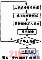
3 Conclusion Based on Samsung's S3C6410 processor and Wi-Fi technology, this system can complete 8 frames/second wireless video transmission and provide better image quality (JPEG quality factor 50). The image receiving end can complete real-time decoding of JPEG pictures. Suitable for low frame rate video transmission applications, such as slide show, computer operation demonstration, teaching, etc. The hardware cost of the video receiving end in the system can be controlled within 600 yuan. It finds a good balance between image frame rate, image quality, processing power requirements at the transmitting end, and system cost at the receiving end.
.FR4,1.0-1.6mm,1oz,Green solder mask,White overlay,HAL
.Electrical testing
.Standard 5 working days