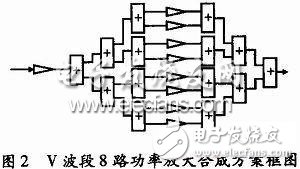
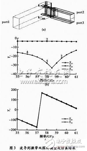
The power amplifier is an indispensable key component of the millimeter wave band transmitter. The output power determines the range and anti-interference ability of the whole system. In millimeter-wave systems, as the frequency increases, the output power of a single MMIC chip can no longer meet the actual use requirements, especially in the non-atmospheric window band. Since the transmission of electromagnetic waves in this band is absorbed by oxygen molecules and water vapor molecules, the attenuation is severe. . Generally used in military secrecy work and close-range radar detection and communication systems, the corresponding device output power is also small. Therefore, the power synthesis method is often used to combine multiple amplifier units to achieve larger power output. The amplifier operates in the V-band and is used in a missile close-range detection system to make full use of the attenuation characteristics of the non-atmospheric window band for privacy and anti-interference. 1.1 Technical requirements According to the basic requirements of the system, the main technical specifications of the amplifier: working bandwidth 2 GHz; output power ≥ 200 mW; gain 20 ~ 25 dBm; input and output port WR15. 1.2 Selection of power devices In order to meet the requirements of the technical specifications, a three-terminal FET power amplifier component with a wide operating band is selected. Eudyna Devices' FMM5715X is selected as the power synthesis unit, and the FMM5715X is a multi-tube composite power monolith with 50 Ω matching in the port impedance. Operating frequency is 57-64 GHz; operating temperature range: -45 to +85 °C, storage temperature range -55 to +125 °C; maximum allowable input power 3 dBm; single-supply operation, DC offset 3 V/150 mA The typical performance at 60 GHz is P1 dB of 16 dBm, saturation power of 17 dBm, and small signal gain of 17 dB. The characteristic parameters are shown in Figure 1. 1.3 Synthetic network design 1.3.1 Synthetic network overall plan In the V-band, the single-tube output power is far from the power output requirement. Even with the MMIC power device with multi-tube synthesis, the single device can not meet the technical specifications. Therefore, the power synthesis technology using multiple devices is an inevitable choice for completing this project. At present, the more mature power synthesis technology is a two-way bridge with better port standing wave, and multi-channel synthesis is realized by multi-stage cascade. The designed amplifier adopts two-channel binary multi-stage power synthesis technology based on the waveguide low-loss transmission line structure. The composite network consists of two parts, a power drive stage and a power amplification synthesis stage, each part including a 3-level binary network, and a waveguide branch line. The bridge and the waveguide-microstrip transition are composed. The synthetic network block diagram is shown in Figure 2. For 8 channels of power distribution, the network loss for each stage is 0.3 dB and the path loss is 0.5 dB. To make the power device saturate during all synthesis, the input power of the FMM5715X should be “2 dBmâ€, after counting the above losses, convert to The power at the input of the power distribution network is 12.4 dBm. Obviously, the driver stage is sufficient for this requirement by a single FMM5715X. When all the power devices in the composite network are in saturated operation, the single-stage loss is 0.3 dB, and the 3-stage power is synthesized. The synthesis efficiency caused by the loss is 80%; if the maximum amplitude and phase imbalance between the combined branches are calculated 3 dB, 30 °, respectively, causing the corresponding synthesis efficiency to be 90%; for 8-way power synthesis, the total synthesis efficiency is When the device is saturated, the 8-way composite output is 17+7.07=24.07 dBm or 255 mW, which meets the technical specifications. The loss of each part of the circuit is 4 8 dB, and the small gain of the entire composite amplifier is about 29.2 dB. 1.3.2 Two-way power distribution/synthesis network In the study of millimeter-wave solid-state integrated power synthesis technology, there is a two-way waveguide microstrip integrated power distribution/synthesis network, as shown in Figure 3. The structure is inserted by the opposite surface microstrip probes through the waveguide E plane to realize in-phase broadband power distribution/synthesis, and at the same time complete the transition between the waveguide and the microstrip. The two microstrip lines are in a face-to-face position. When integrated with solid-state power devices, they provide a good heat dissipation path to ensure reliable operation and performance. In order to obtain sufficient solid-state power device mounting space, the waveguide size of the composite network is appropriately increased. To meet the standard waveguide port conditions, an appropriate waveguide impedance transform segment is selected according to the working bandwidth requirement. Electromagnetic field analysis shows that the structure loss is "2 dB" in the range of 55 to 60 GHz, which is equivalent to a single waveguide microstrip transition structure; due to structural symmetry, the two microstrip ports have good amplitude and phase balance characteristics. 1.3.3 V-band 3 dB waveguide branch bridge The power synthesis of two or more stages needs to be based on the wave conductive bridge. The low loss, wide frequency band and good port standing wave and branch isolation of the bridge are the prerequisites for stable and reliable power synthesis technology. Since the relative bandwidth required by this project is relatively narrow, the three branch sections can be used to meet the index requirements. In the structure, considering the achievability of the bridge processing, the cross-section size of the bridge waveguide is appropriately increased, and the length of the coupling hole of the waveguide branch section is reduced, and the width is increased, so that all processing dimensions are 1 mm, which reduces the difficulty of machining and improves. Corresponding error capacity reduces processing costs. This structural improvement reduces the connection discontinuity of the branch bridge and the waveguide-microstrip three-port network in the composite network. KNM3 Series Moulded Case Circuit Breaker
KNM3 series Moulded Case Circuit Breaker is MCCB , How to select good Molded Case Circuit Breaker suppliers? Korlen electric is your first choice. All moulded Case Circuit Breakers pass the CE.CB.SEMKO.SIRIM etc. Certificates.
Moulded Case Circuit Breaker /MCCB can be used to distribute electric power and protect power equipment against overload and short-current, and can change the circuit and start motor infrequently. The application of Moulded Case Circuit Breaker /MCCB is industrial.
KNM3 series Molded Case Circuit Breaker,Small Size Molded Case Circuit Breaker,Electrical Molded Case Circuit Breaker,Automatic Molded Case Circuit Breaker Wenzhou Korlen Electric Appliances Co., Ltd. , https://www.zjmotorstarter.com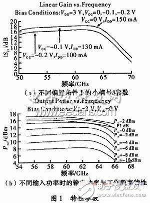

Korlen electric also provide Miniature Circuit Breaker /MCB. Residual Current Circuit Breaker /RCCB. RCBO. Led light and so on .