This article refers to the address: http:// Abstract: Due to the large number of signals collected and the complex signal transmission, the traditional vehicle driving recorder often cannot guarantee the accuracy of the terminal to obtain data. The CAN bus is applied to the design of the vehicle tachograph, and the CAN bus controller SJA1000 and the CAN bus transceiver TJAl050 are used to realize remote multi-point data communication between the car tachographs. The hardware design principle and software design flow of the CAN bus interface circuit of the vehicle driving recorder are given. The use of the CAN bus improves the stability of the vehicle tachograph, making the data transmission of the car tachograph more reliable and more convenient to use.
Key words: CAN bus; vehicle traveling recorder; SJAl000; CAN controller; CAN bus transceiver
A vehicle traveling data recorder is a digital type that is installed on a vehicle and can record, store, display, and print the vehicle's running speed, time, mileage, and other state information about the vehicle's travel, and can realize data output through the interface. Electronic recording device, commonly known as car black box. The use of the vehicle tachograph has an important role in curbing the traffic violations such as fatigue driving, vehicle overspeed, restricting the driver's poor driving behavior, ensuring the driving safety of the vehicle and road traffic accidents.
The vehicle travel recorder (hereinafter referred to as the recorder) is composed of a host part of the vehicle travel recorder and a data analysis software part of the computer terminal. The main part is the core of the recorder, which mainly completes the collection, recording and storage of vehicle driving data. Traditional car tachographs have many sampling signals, and the signal acquisition is very complicated. Many connecting wires are needed. In order to ensure the accuracy of the collected signals, the collected signals are processed through the amplifying circuit and the filtering circuit, if the circuits are between the levels. Poor matching of electrical characteristics will affect the accuracy of the signal acquisition of the recorder, and sometimes even affect the normal operation of other systems in the car.
The data analysis software of the computer terminal mainly realizes the analysis and processing of data such as speed and pressure during the running of the automobile. Therefore, the signal collected by the recorder must be transmitted with the computer terminal, the peripheral alarm module, the human-machine interface module and the like. The standard RS232 serial communication is a mature and stable communication method, and it must be the communication method required by the national standard of the vehicle tachograph. However, the RS232 serial communication signal has a short distance and can only perform point-to-point communication, and cannot directly set up a multi-point communication network. In order to extend the communication distance of RS232 and form the RS232 node into the communication network, it is necessary to convert the RS232 serial communication interface into a CAN bus interface, and form a remote multipoint communication network in the form of a CAN bus.
The application of CAN bus enables the car tachograph to directly read the corresponding signals from the CAN bus through the interface, thus not affecting the normal operation of other systems; at the same time, the CAN bus has the advantages of high reliability of data transmission and also makes its data accuracy. Guaranteed.
1 CAN bus characteristics Controller Area Metwork (CAN) bus is a multi-host local network. The CAN bus specification has been developed as an international standard by the International Organization for Standardization (ISO). C-AN bus belongs to the bus serial communication network. Because it adopts many new technologies and unique designs, it has the following characteristics: 1) The bus works in multi-master mode, the communication mode is flexible, and it does not need to occupy node information such as address; 2) The node information on the CAN bus network is divided into different priorities to meet different real-time requirements. 3) Non-destructive bus arbitration technology is adopted, and the network is not in the case of heavy network load; 4) Only Packet filtering can be used to transmit and receive data in several ways, such as point-to-point, point-to-multipoint and global broadcast, without special “schedulingâ€; 5) direct communication distance up to 10 km (rate 5 Kb/s or less) 6) Communication rate up to 1 Mb/s (the communication distance is up to 40 m at this time); 7) Each frame of information has CRC checksum and other error detection measures to ensure that the data error rate is extremely low; The CAN bus node has the function of automatically turning off the output in case of a serious error, so that the operation of other nodes on the bus is not affected.
2 CAN bus interface hardware circuit design principle CAN bus is a multi-master bus, which can be used as a node of the car CAN network. The node connected to the computer terminal in the system is the master node, and the other nodes are slave nodes. In theory, there can be more than one master node. In a simple system, generally only one master node is set, and the master node sends configuration data to the slave node, and the master node requests the slave node for the current working state, current data, and data management. The slave nodes perform different functions according to the needs of the application, such as field data collection, device control, and driving, and can implement communication functions such as uploading data and receiving data.
The master node is composed of a PC, a CAN interface circuit, and a host computer interface software. The CAN interface circuit realizes the communication between the slave node and the host computer on the CAN bus. The block diagram of the CAN interface circuit is shown in Figure 1. 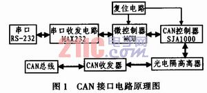
The CAN interface circuit uses PHILIPS' P89C52 microcontroller as the core processor, which is responsible for the initialization of the CAN bus controller, and the read/write control of the CAN controller through the data bus to realize the transmission and reception of information in the CAN network node. On-site control; serial communication is realized by the MAX232 and the PC, and the data sent by the PC is written to the microcontroller, and then by the microcontroller. The I/O port and the control signal line write data to the CAN controller and send it to the CAN bus through the CAN transceiver. On the CAN bus, the data that needs to be uploaded to the master node is written to the CAN controller via the CAN transceiver, and the interrupt signal is transmitted. Remind the microcontroller to read and upload it to the PC via the RS-232 interface. At both ends of the CAN bus, a 120 Ω matching resistor is required to improve the anti-interference ability and overall reliability of data communication.
3 main hardware circuit design In addition to the main control device microprocessor P89C52, CAN bus interface circuit is mainly composed of CAN bus communication interface circuit, CAN transceiver and optical isolation part, serial transceiver.
3.1 CAN bus communication interface circuit CAN bus communication interface circuit is a very important link, the correct operation of the recorder is closely related. The design uses the bus controller SJA1000 manufactured by PHILIPS, a stand-alone CAN bus controller designed for regional network control in mobile targets and general industrial environments. SJA1000 has PCA82C200 mode (ie default Basic CAN)
Mode), the basic characteristics are as follows: 1) with PCA82C200 mode (ie default Basic CAN mode); 2) support CAN2. OA and CAN2. OB protocol; 3) support 11-bit and 29-bit identifiers; 4) communication bit rate up to 1 Mb/s; 5) using 24 MHz clock frequency; 6) can be connected to different microprocessors; Programmable CAN output driver configuration; 8) Wide temperature adaptation range (-40 ~ +125 ° C).
In addition, it has PeliCAN mode extension functions: 1) readable/accessible error count register; 2) programmable error alarm limit register; 3) last error code register; 4) interrupt for each CAN bus error; 5) Arbitration loss interrupt with specific bit representation; 6) Single transmission (no repetition); 7) Listen only mode (no acknowledgement, no active error flag); 8) Support hot swap (software bit rate detection); 9) Extension of the acceptance filter (4-byte acceptance code, 4-byte mask); 10) Receive self-message (self-receive request).
Figure 2 shows the SJA1000 and microprocessor communication interface circuit. The reset signal RST of the SJA1000 is active low. 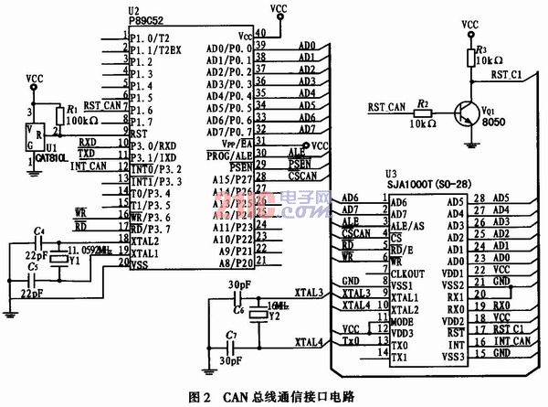
3.2 CAN bus transceiver isolation circuit CAN bus transceiver uses the standard high-speed CAN transceiver TJAl050, the transceiver is the interface between the CAN protocol controller and the physical bus. The TJAl050 provides differential transmit performance for the bus and differential receive performance for the CAN controller. In addition to enhancing EMC, another important feature of TJAl050 is that the CAN bus exhibits passive characteristics when power is not applied. This makes the TJAl050 much superior in performance to other CAN bus transceivers. The TJAl050 has two modes of operation, high speed and mute, all controlled by pin S. The pin S is grounded to enter the high speed mode. Since the pin S has an internal pull-down function, the high speed mode is also the default mode when it is not connected. In high-speed mode, the bus output signal has a fixed frequency and switches at the fastest possible speed for the maximum bit rate and maximum bus length. Connect pin S to a high level to enter silent mode. In silent mode, the transmitter is disabled regardless of the TXD input signal. Therefore, in the non-transmitting state, the TJA1 050 consumes the same power supply current as in the invisible state. The lowest baud rate of TJAl050 is 20 Kb/s.
In order to ensure that the controller can operate normally when the CAN bus is seriously disturbed, the CAN bus controller is not directly connected to the bus transceiver module, but is connected through the optical isolator 6N137, thereby achieving electrical isolation between the nodes on the bus. The circuit diagram is shown in Figure 3. The 6th pin Vo output circuit of the 6N137 optocoupler belongs to the open collector circuit and must pull up a resistor. In addition, there is an LED between the 2nd pin and the 3 pin, and a current limiting resistor must be connected in series. The two power supplies VCC used in the optocoupler section and the +5 V of the CAN must be completely isolated. 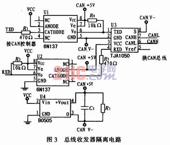
3.3 RS232 bus interface module RS232 bus interface mainly realizes the RS232 serial port communication function between the vehicle drive recorder and the PC. The MAX232 chip is a commonly used RS-232C and TTL level converter. It has a voltage multiplying circuit and a conversion circuit inside. It can realize RS-232C and TTL level conversion with only +5 V power supply. It is easy to use and can be used in one chip. Connect 2 pairs of receiving/transmitting lines. Therefore the converter uses the MAX23 2. The interface schematic diagram is shown in Figure 4. 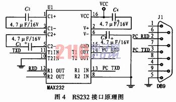
4 Software Design Before software design, in order to ensure that the chip select address of SJAl000 does not conflict with other external memory, first determine the base address and reset pin of SJAl000, and then initialize SJAl000 correctly. The main flow chart of the software design of the CAN interface circuit is shown in Figure 5. It mainly includes the initialization of the CAN controller, data transmission, data reception and error handling. 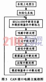
The initialization of SJAl000 can only be performed in the reset mode. The initialization mainly includes the setting of the working mode, the setting of the receiving filtering mode, the setting of the receiving mask register and the receiving code register, the setting of the baud rate parameter and the setting of the interrupt enable register. The initialization process is shown in Figure 6. 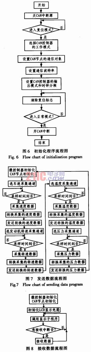
The CAN transmission data flow is shown in Figure 7, and the data reception process is shown in Figure 8. This program takes the example of collecting travel speed and pressure data of a traveling vehicle.
5 Conclusion The application of CAN bus simplifies the signal sampling system of the vehicle tachograph, reduces the performance requirements of the MCU processing unit, improves the stability of the vehicle tachograph, and establishes multi-point remote communication in the RS232 communication node. Both hardware and software design innovations make the recorder easier to install, cost-effective, and highly portable and expandable.