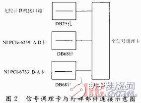
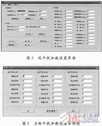
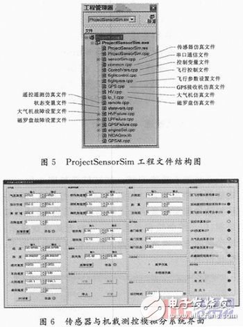
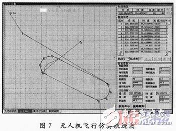
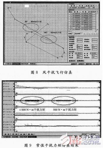
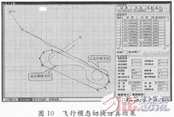
As a target for simulating aircraft, the UAV can provide aerial targets for fire control radar flight and shooting tasks of air defense weapon systems. It is an indispensable equipment in the development and identification of weapon systems. As one of the core components of the UAV, the flight control system completes the mission of the UAV in various modes by controlling the attitude of the UAV. The existing test methods for a UAV flight control system include discrete component testing and complete machine testing after component installation. Both methods are routine static tests, complex organization implementation, low test efficiency, long task preparation cycle, and the dynamic performance of the actual flight process of the drone cannot be verified, and it is difficult to locate the faults in the test. The environmental interference factors (mainly wind interference) and the flight conditions of the UAV after the sensor failure cannot be simulated, so that the flight control strategy correction cannot be targeted. To sum up, the task of developing a semi-physical simulation platform for the UAV flight control system is particularly urgent. The platform takes the existing UAV flight control system as the test object, and mainly completes the following functions: (1) Combine with the UAV flight control computer, electric steering gear, throttle motor and other physical objects to complete the simulation test of the flight control system; (2) Simulating the flight performance under the conditions of wind disturbance and torque interference, and displaying the flight path, rudder angle and rudder yaw rate of the drone in real time in a two-dimensional curve; (3) It is possible to set the fault of some sensors of the UAV flight control system and simulate the flight mode under fault conditions. The semi-physical simulation platform consists of two parts: hardware device and application software. The hardware equipment includes a new flight system analog subsystem, sensor and airborne measurement and control analog subsystem, remote/telemetry simulation subsystem, command and display subsystem, drone shape display subsystem, and existing flight control computer and flight control. Computer interface box, electric steering gear, throttle motor and other physical objects. The application software includes applications for creating new subsystems. The block diagram of the principle of the semi-physical simulation platform is shown in Figure 1. The working principle of the semi-physical simulation platform is as follows: the sensor and the onboard measurement and control simulation subsystem exchanges the rudder angle, angular rate, throttle opening, remote command, external interference and other information of the drone through the interface box and the flight control computer, and The flight system simulation subsystem transmits the sampled and converted flight control computer execution results, and transmits the telemetry information (including the simulation data of the sensor and the onboard measurement and control simulation device, the fault state, the remote command command, etc.) to the remote control/telemetry analog subsystem. After receiving the information for calculation, the flight control computer controls the electric steering gear and the throttle motor to perform corresponding actions, and returns the execution result to the sensor and the onboard measurement and control simulation subsystem. The flight system simulation subsystem sends the solved aircraft state parameters to the UAV's shape display subsystem. After the solution, the UAV's attitude, throttle opening and altitude changes are displayed in three-dimensional animation. The command display subsystem will display the position, altitude and speed information of the drone received on the digital map, and issue the command password in a timely manner, and the operator will interfere with the flight of the drone. The three-dimensional shape, measurement and control data, and command display interface of the drone are displayed on the projection screen by the KVM switch. (1) Application software running platform selection principle Since the platform belongs to the fixed test equipment, the hardware of the application software running platform of each sub-system should adopt the rack-type industrial computer or desktop computer as much as possible. The number and type of the motherboard slots should be relatively abundant, so as to facilitate the existing hardware boards. The installation and subsequent functionality of the platform is expanded. (2) The selection principle of the data acquisition card: one is to ensure the number of channels; the second is to ensure the sampling frequency; the third is to ensure the data resolution. (1) Sensor and onboard measurement and control simulation subsystem The subsystem includes a large number of signal acquisition, switching and processing tasks, and the hardware uses an industrial computer architecture. Configure the data acquisition card, multi-port serial card and self-developed signal conditioning card to complete data collection and information exchange. The specific hardware model and basic parameters are: The industrial computer selects Siemens 547B: 64-bit CPU processor, 4 PCI slots, 1 PCI-Ex16 graphics expansion interface. Multi-port serial card adopts MOXA CP 118U: 4-channel RS 232/422/485 PCI serial port, serial communication rate is 921.6 Kb/s; onboard 1 5 kVESD surge protection. D/A card selects NI PCI-6733: 8 channels D/A, data update rate 1 MS/s (16b), 8 channels Ning I/O. The A/D card uses NI PCIe-6259: 4-channel D/A, data update rate is 1 Ms/s (16 b), 32 channels of A/D channels; A/D sampling rate is 2.8 MS/s ( 16 b), 48 digital I/O. The DIO card uses NI PCIe-6503: 24 digital I/O. (2) Flight system simulation subsystem, remote control/telemetry simulation subsystem These two sub-systems mainly carry out the transmission and solution of drones and measurement and control data. The hardware composition is relatively simple. The general commercial desktop computer with multiple types of motherboard slots can be selected, and the MOXA CP118U multi-port serial card is configured. (3) Command display subsystem, drone shape display subsystem These two sub-systems are mainly for the operation of command and display application software, and can be selected from ordinary commercial desktop computers with various types of motherboard slots. When the sensor and the onboard measurement and control analog sub-system and the remote control/telemetry analog sub-system, the flight system analog sub-system, the flight control computer interface box and other parts exchange data, the signal conversion is completed by D/A, A/D, DIO board. It will be affected by the complex electromagnetic environment inside the chassis, resulting in a strong noise on the output signal, which needs to be filtered. In addition, since the input and output voltage of the flight control computer interface box are both +27 V, and the D/A, A/D, and DIO boards work at +5 V, it is necessary to design the signal conditioning card to complete the signal filtering and working voltage. Conversion. The schematic diagram of the connection between the signal conditioning card and the external components is shown in Figure 2. The platform application software includes five application softwares: flight system simulation subsystem, drone shape display subsystem, sensor and airborne measurement and control simulation subsystem, remote/telemetry simulation subsystem, and command display subsystem. Mainly by solving the UAV dynamics model, the UAV's attitude, engine and other information are obtained, and the UAV flight simulation is realized. The simulation process considers the binding of wind interference and torque interference at the same time. (1) Selection of application software development environment Because of the need to solve the dynamic model of the drone, considering that VC++6.0 has a large number of function calculation libraries, its data calculation ability is more prominent, so VC++6.0 is selected as the application software development environment. (2) Establishment of drone dynamics model The establishment of the drone dynamics model is the basis of the flight system simulation. Based on the reference, the drone dynamics model is established. (3) Loading of wind disturbance and torque disturbance The wind disturbance simulation mainly decomposes the wind speed and wind direction onto the axis of each body, and then combines the three-way velocity equation in the aerodynamic equations to solve the three-way velocity. After the solution into the dynamic model, the wind disturbance is obtained. Aircraft attitude parameters. The method of loading the torque disturbance takes the form of directly setting the corresponding parameters in the dynamic model. Set the content packet interference torque, forward and reverse pulse interference, start time, end time, and the magnitude of the constant torque. (4) Implementation of application software After the application software is completed, in order to prevent the mis-modification generated in the software programming process of other subsystems, the UAV model is provided by the dynamic link library (UAVSimu.DLL), and the setting of the external torque is completed through the interference setting interface. 3, as shown in Figure 4. It can simulate sensor characteristics such as GPS receiver, magnetic heading, and atmospheric data computer, and output it to each relevant subsystem through digital or analog signals for actual platform simulation. The types of faults that can be set include: GPS receiver failure, heading jump, big data computer height jump. (1) Selection of application software development environment Because the application software needs a lot of software interface development during the design process, the biggest advantage of Borland's C++Builder integrated development environment is the direct drag-in method in the software interface development process, which greatly facilitates engineering development. Therefore, C++Builder is used for application software development. (2) Software overall design and construction Create a project file of "ProjectSensorSim", including the project file shown in Figure 5. After running the project file, generate the subsystem software interface, as shown in Figure 6. The sub-system is used to simulate the basic functions of the ground monitoring station, and is used to complete the transmission of remote command and the reception of telemetry data. The software adopts modular design, including two-dimensional curve drawing, route binding, saving and deleting, track drawing, serial port processing, telemetry data receiving, telemetry information processing, remote command processing and other modules. The shape display subsystem uses VC++2010 software and is developed based on OpenGL. The software module includes: a communication interface module, a three-dimensional demonstration module, a meter display module, and the like. (1) Reduce the time delay between systems Due to the distributed and modular structure, communication between the sub-systems through the serial port will inevitably cause communication delay problems. In the software design process, the following measures are taken to solve: 1 reduce the simulation step size of the flight system simulation software and increase the continuity of flight parameters; 2 Improve the serial port baud rate of attitude information transmission between flight system simulation, sensor and airborne measurement and control simulation and flight control computer simulation three sub-systems; 3 Optimize the frame structure of the serial data communication between the sensor and the onboard measurement and control analog subsystem and other subsystems; ensure that the attitude information reaches the flight control computer in the shortest time. (2) Real-time processing technology of industrial equipment data Since the sensor and the onboard measurement and control analog sub-system use the industrial computer architecture, it is necessary to simultaneously perform data communication with multiple subsystems such as flight system simulation, and all tasks are required to be completed in milliseconds. In software design, the application of MulTImedia TImer (multimedia timer) combined with multi-threading in Windows environment is realized. The application multimedia timer is an accurate timer supported by the computer from the hardware, and the timing error can generally reach ten microseconds, which can fully meet the real-time requirements. Connect the various components of the platform according to Figure 1, run each application software, and perform basic system function tests. The test results are shown in Figure 7. The drone can complete the flight simulation according to the pre-bound route; the remote control/telemetry simulation software can display the attitude information of the drone and the sensor simulation information in real time, and display it visually in the form of two-dimensional curves and status indicators; The method vividly displays the attitude and height changes during the flight of the drone. (1) Simulation in wind interference mode In the flight system simulation subsystem, the wind disturbance is set to 90°, 80 m/s in the north direction and 180° in the north direction, 80 m/s through the “wind disturbance†function button, and observe the flight path change of the drone. As shown in Figure 8. It can be seen that after the drone is disturbed by the wind, the track changes significantly in a short time, and then the flight control system can correct the deviation of the route in time, so that the drone can fly according to the scheduled route. (2) Simulation under the action of disturbance torque In the flight system simulation subsystem, the external disturbance torques of 1000 N·m and 500 N·m are set separately, and the simulation of the drone in this interference situation is observed, as shown in Fig. 9. It can be seen from the figure that the rudder angle and the rudder angle rate of the UAV under different moments are different. In the case of applying disturbance force/torque, the attitude of the drone has changed significantly. The flight control system eliminates the influence of external disturbance by continuously adjusting the rudder angle and the rudder angle to ensure that the drone can follow the predetermined attitude. Normal flight. During the autonomous flight of the drone, the sensor is set to simulate the fault, and after the "manual guidance" command is sent, the drone enters the remote command flight mode. Send remote commands such as right, direct, and left to observe the flight path of the drone. After the "manual guidance" mode is completed, the sensor failure is cancelled, and then the "autonomous flight" command is sent, and the drone re-enters the autonomous flight state. The flight control system automatically adjusts the flight parameters and flies to the set waypoint, as shown in Figure 10. Show. This paper introduces the basic functions, overall technical solutions, hardware selection schemes and software design schemes of the semi-physical simulation platform of the UAV flight control system. Finally, the basic functions of the platform were tested and verified. The platform can be used not only for the simulation test of the flight control system, but also for the flight law research of the drone, the flight performance evaluation, and the simulation training of the control personnel. Shenzhen Ruidian Technology CO., Ltd , https://www.wisonen.com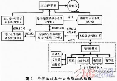
Analysis of the design scheme of the semi-physical simulation platform for the UAV flight control system
0 Preface