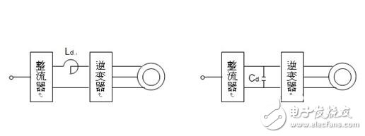
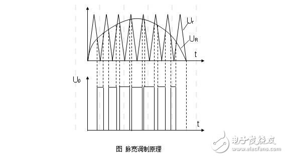
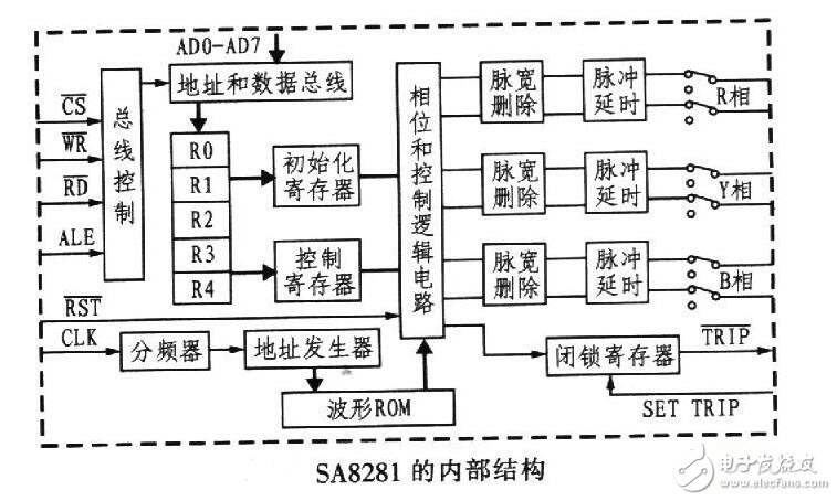
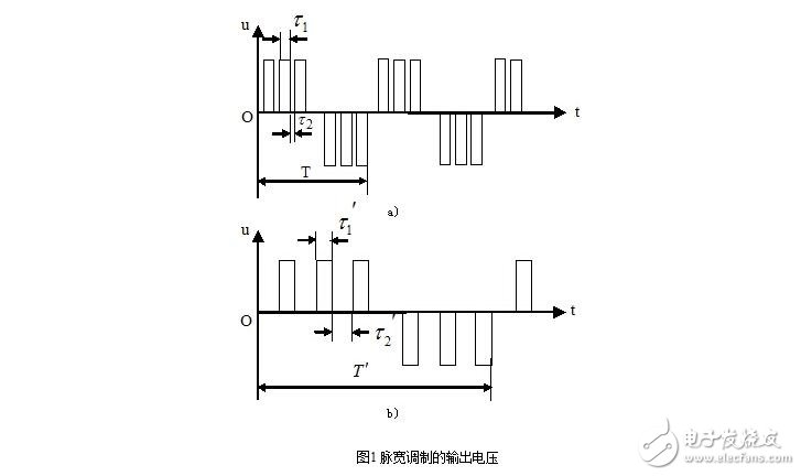
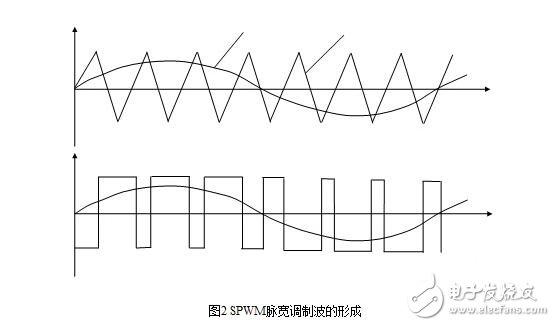
The SPWM (Sinusoidal PWM) method is a relatively mature one, and currently uses a wider PWM method. An important conclusion in the aforementioned sampling control theory is that the effects of the narrow impulses with equal impulses and different shapes are basically the same when they are applied to the inertia. The SPWM method is based on this conclusion. The PWM waveform, which is equivalent to the sine wave, and the SPWM waveform, which is equivalent to the sine wave, is used to control the on/off of the switching device in the inverter circuit to make the area of ​​the pulse voltage output. It is hoped that the output sine wave has the same area in the corresponding interval, and the frequency and amplitude of the output voltage of the inverter circuit can be adjusted by changing the frequency and amplitude of the modulated wave. Spwm frequency control principle The working principle of SPWM frequency conversion speed regulation: The pulse width modulation technique utilizes the concept of "modulation" in communication technology, using a desired waveform as a modulated wave and a modulated signal as a carrier. SPWM control mode: The SPWM modulated wave is based on the intersection of the triangular wave and the sine wave to determine the on/off operation timing of the inverter switching device. Spwm application Principle of SA8281 SPWM Wave Generator and Its Application in Frequency Converter The pulse width modulation technique controls the on and off of the switching elements by a certain law to obtain a set of rectangular pulse waveforms of equal width and not equal width for approximating the sinusoidal voltage waveform. The application of pulse width modulation technology in inverters greatly promotes the development of modern power electronics technology and modern speed control systems. In recent years, due to the continuous emergence of field-controlled self-shutdown devices, the corresponding high-frequency SPWM (sinusoidal pulse width modulation) technology has been widely used in motor speed regulation. SA8281 is an integrated circuit for three-phase SPWM wave generation and control introduced by MITEL. It has convenient interface with microprocessor, built-in waveform ROM and corresponding control logic. After setting, it can independently generate three-phase PWM waveform. The intervention of the microprocessor is required when the output frequency or amplitude needs to be changed, and the microprocessor only controls it in a small amount of time, thereby enabling the detection of the entire system. Protection and control, etc. The inverter based on SA8281 and 89C52 has a simple circuit. full functioning. The performance price ratio is high. Good reliability and other advantages. MCU generation Many single-chip microcomputers used in the market have the function of generating SPWM control waveforms, and the external waveform driving circuit can drive the power bridge to achieve the purpose of inverter. It should be said that as long as the microcontroller with the PWM module and the timer module can accomplish this task. The specific implementation is to first assign the sine table to the array. Then, the PWM waveform generation module enters an interrupt every PWM cycle, and changes the value of the PWM comparator according to the sine table in the ISR, and sequentially cycles. SPWM frequency conversion speed regulation method in AC servo motor One of the key components in the AC motor variable frequency speed control system is the inverter. Due to the requirements of speed regulation, the inverter must have the functions of continuously adjustable frequency, continuous adjustable output voltage, and a certain proportional relationship with frequency. Variable frequency and variable voltage can be realized by using pulse width modulation inverter. As shown in the figure, since the average value of the voltage is proportional to the duty ratio, when the frequency is adjusted, the duty ratio of the output voltage pulse is changed, and the frequency conversion and the voltage transformation can be simultaneously realized. Compared with FIG. 1(a), the voltage period shown in FIG. 1(b) is increased (the frequency is lowered), and the duty ratio is decreased, so that the average voltage is lowered. When the PWM method is used to control the on/off of the inverter tube, a set of rectangular pulses with the same amplitude and the same width can be obtained. The width of the rectangular pulse can be controlled to control the output voltage, and the modulation period can be controlled to control the output frequency. Pressure and frequency conversion. Since the output voltage waveform is a rectangular wave, it has many high-order harmonic components. For the motor, what is useful is the fundamental of the voltage. In order to reduce the influence of harmonics and improve the running performance of the motor, a symmetrical three-phase sine wave power supply should be used to supply the three-phase AC motor. The output of a sinusoidal pulse width modulation inverter (SPWM) can obtain a set of rectangular pulse waveforms of equal width and not equal width to approximate an equivalent to a sinusoidal voltage wave. SPWM pulse width modulation waveform, as shown in Figure 2. When the sine value is the maximum value, the pulse width is also the largest, and the pulse interval is the smallest. Conversely, when the sine value is small, the pulse width is also small, and the pulse interval is large. Such a series of voltage pulses can greatly reduce the harmonic components in the load current. A SPWM inverter with digital circuitry can be implemented in a software-based control mode. The advantage is less hardware, flexibility and intelligence. The disadvantage is that the pulse width of the SPWM needs to be determined by calculation, with a certain delay and response time. With the development of high-speed, high-precision multi-function microprocessors, microcontrollers and SPWM-specific chips, digital SPWM technology using microcomputer control has occupied the leading position of today's PWM inverters. SPWM variable frequency speed control system, the function of each part: Speed ​​reference: Given signal, control frequency, voltage and forward and reverse. Smooth start loop: The start acceleration and deceleration time can be set with the mechanical load to achieve the purpose of soft start. Function generator: keep the motor air gap flux constant when outputting low frequency signals, and compensate for the influence of stator voltage drop. Voltage-frequency transformer: converts the voltage into frequency, generates a square wave through a frequency divider and a ring counter, and sends it into the modulation loop together with the triangular wave generated by the triangular wave generator. Voltage regulator: Generates a sine wave with adjustable frequency and amplitude, sends it into the modulation loop, feeds it into the modulation loop, and performs SPWM conversion in the modulation loop to generate a three-phase pulse width modulation signal. In the base circuit, the signal is output to the base of the power transistor, that is, the main circuit of the SPWM is controlled to realize the frequency conversion speed regulation of the permanent magnet AC servo motor. Current Detector: Overload protection. This scratch-resistant TPU Film protects your new AirTag from daily wear and tear. It can be easily glued to the back to keep the shiny silver in its original condition. In addition, the AirTag screen protector with "self-healing" function can automatically repair small scratches and bubbles within 24 hours. This means you can continuously enjoy the new look and appearance of AirTag without worrying about serious scratches and dents. Apple Airtag Screen Protector, Apple Airtag Screen Protective Film, Apple Airtag TPU Film, AirTag Tracker Screen Protector, Skin Wrap Shenzhen Jianjiantong Technology Co., Ltd. , https://www.jjttpucuttingplotter.com
The Apple Airtag TPU Film can perfectly fit your AirTag skin. It is designed to provide the maximum coverage for your AirTag metal panels. Compatible with most AirTag shells. Leave extra space around the frame so that your shell can wrap the edges of the AirTag without interfering with the film.
The 0.14mm ultra-thin AirTag Screen Protector allows you to enjoy the maximum resolution while being thin enough to make the AirTag sensitive to the original signal response, ensuring that it will not affect any user experience. You won't even notice that the screen protector is there, so your Apple logo can still be displayed.
The AirTag Tracker Screen Protector is very easy to apply and is specially designed for your AirTag. Just clean your AirTag and install it on the surface to eliminate all bubbles and get the job done!