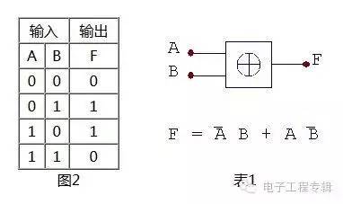
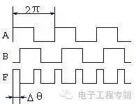
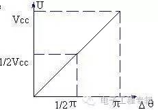
The meaning of phase lock is the automatic control of phase synchronization. The closed loop system that can complete the phase synchronization of two electrical signals is called phase-locked loop, which is called PLL. It is widely used in technical fields such as broadcast communication, frequency synthesis, automatic control and clock synchronization. A typical phase-locked loop (PLL) system consists of three basic circuits: phase detector (PD), voltage regulator (VCO) and low-pass filter (LPF), as shown in Figure 1. First, the phase detector (PD) constitutes a phase detector with many circuit forms. Only two phase detectors used in the experiment are introduced here. 1. The logical truth value of the XOR gate of the XOR gate detector is shown in Table 1, and Figure 2 is a logical symbol diagram. It can be seen from Table 1 that if the input terminals A and B respectively send a signal waveform with a duty ratio of 50%, when there is a phase difference Dθ between the two, the duty ratio of the waveform of the output terminal F is related to Δθ, as shown in FIG. . Smoothing the F output waveform through the integrator, the integrator outputs the average of the waveform, which is also related to Δθ, so that we can use the XOR gate to perform phase-to-voltage conversion to form a phase detection circuit. Then the average value (DC component) after integration by the integrator is: U = Vdd * Δ θ / π (1) Different Δθ have different DC components Vd. The relationship between Δθ and V can be described using FIG. As can be seen from the figure, the two have a simple linear relationship: Ud = Kd * Δθ (2) Kd is the phase sensitivity image 3 Figure 4 2. As mentioned before the edge-triggered phase detector, the XOR gate phase comparator requires two signals to be compared to have a 50% duty cycle, which brings some inconvenience to the application. The edge-triggered phase detector compares the signal by comparing the upper edge (or lower edge) of the two input signals, and does not require the duty cycle of the input signal. Right Angle D-sub Connector IP66 IP67 Rated
IP66 / IP67 waterproof d-sub connectors-Designed for IP Performance
ANTENK has developed IP66 / IP67 waterproof d-sub connectors that utilize a proprietary sealing technology, which maintains the same physical size and footprint as standard d-sub products.
Antenk's line of Waterproof d-sub connectors utilize an innovative sealing technology eliminating the need to redesign enclosures and PC boards when implementing IP67 design upgrades.These connectors are designed for applications that require protection from heavy spray or are exposed to short-term submersion. Connectors are available in vertical and right angle board mount types as well as solder cup for panel mount cable applications. Standard D-Subs are available in 9 pin, 15 pin, and 25 pin positions, and high density D-Subs are available in 15 pin, 26 pin, and 44 pin positions
Right Angle D-SUB Connector IP66 IP67 Rated available in
3 industry sizes/positions:Standard Density (9 pin, 15 pin, 25 pin). Right Angle D-Sub IP67 Rated,Right Angle D-Sub Waterproof,Standard Density Waterproof Right Angle D-Sub Connector, High Density Waterproof Right Angle D-Sub Connector ShenZhen Antenk Electronics Co,Ltd , https://www.pcbsocket.com
Second, the voltage controlled oscillator (VCO) voltage controlled oscillator is an oscillator whose oscillation frequency ω0 is controlled by the control voltage UF(t), that is, a voltage-frequency converter. The characteristics of the VCO can be expressed by a relationship between the instantaneous frequency ω0(t) and the control voltage UF(t). When no control voltage is applied (but it cannot be considered that the control DC voltage is 0, because the voltage at the control terminal should be the superposition of the DC voltage and the control voltage), the oscillation frequency of the VCO is called the free oscillation frequency ωom, or the center frequency, which is linear in the VCO. Within the control range, the instantaneous angular frequency can be expressed as: ωo(t)= ωom + K0 UF(t) where K0 is the slope of the VCO control characteristic curve, often referred to as the control sensitivity of the VCO, or the voltage control sensitivity. .
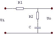
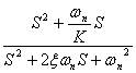
Third, the loop filter Here only the passive proportional integral filter is shown in Figure 5. Its transfer function is: 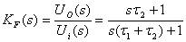
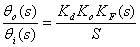
Fourth, the phase model and transfer function of the phase-locked loop 


V. Synchronization and capture of phase-locked loops
The output frequency of the phase-locked loop (or the frequency of the VCO) ωo can track the operating state of the input frequency ωi, called the synchronous state. In the synchronous state, there is always ωo = ωi. Under the condition that the phase locked loop remains synchronized, the maximum variation range of the input frequency ωi is called the synchronous bandwidth and is represented by DωH. Beyond this range, the loop loses lock. When the lock is lost, ωo≠ωi, if you try to change ωi from two directions, make ωi move closer to ωo, and then make Δωo =(ωi-ωo)↓. When Δωo is small enough, the loop enters from loss of lock. Locked state. This frequency range that causes the PLL to undergo frequency pulling and eventually causes the lock to enter is called the capture band Δωp. The timing of the synchronization band ΔωH, the capture band Δωp and the VCO center frequency ωo is as shown in Fig. 7. 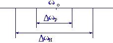
Applications of Antenk waterproof d-sub connectors:
Hand held computers, scanners, and printers that are used outdoors
Remote sensors, gauges, and data loggers that are used outdoors
Industrial and Medical equipment that is routinely subject to wash down
Transmitters and emergency beacons that are subject to temporary submersion
Gas, Electric, and Water metering systems that have embedded Smart Grid electronics
Portable electric generation equipment (Gen Sets)
Consumer and Commercial boating electronics (Radios, Scanners, Radar, DC Power Ports)
IP67 D-SUB | WATERPROOF CONNECTORS FEATURES & BENEFITS
Signal / Low Power in 6 standard size
(Standard: 9 pin, 15 pin, 25 pin; High Density: 15 pin, 26 pin,44 pin)
Combo-D / High Power in a variety of configurations:
(3W3, 5W5, 7W2, 9W4, 11W1, 13W3, 13W6, 17W2, 21W1, 21WA4)
Solder Cup, Vertical Mount & Right Angle Board Mount Options
High Reliability Screw Machined Contacts
3 amp / 5 amp / 20 amp / 40 amp Power Options
-65°C to +105°C Operating Temperature Range
Male & Female Versions
Right Angle D-sub Connector IP66 IP67 Materials
Shell: Steel with Nickel Plating.
Insulator: Glass-filled thermoplastic. U.L. rated 94V-O
(260° process temp for board applications)
Machined Contacts:
Male Pins - Brass
Plating: Gold Flash on entire contact.
IP67 Right Angle D-Sub Seal: Proprietary Information