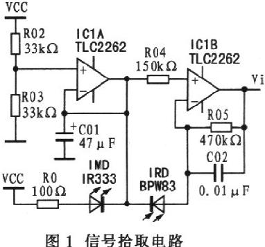
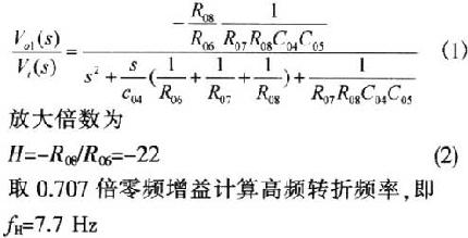
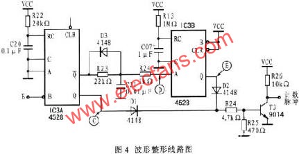
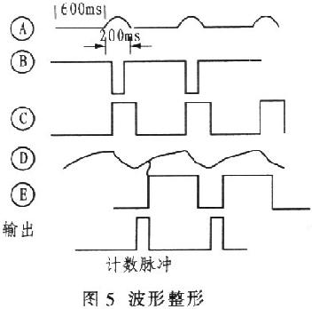
1 Introduction Pulse measurement belongs to the measurement of detecting the presence or absence of pulse. When there is a pulse, the light is blocked. When there is no pulse, the light transmission is strong. The sensors used are infrared receiving diodes and infrared emitting diodes. There are two types of pulse measurement for sports measurement: finger pulse and ear pulse. These two measurement methods have their own advantages and disadvantages. Finger pulse measurement is more convenient and simple. However, because there are many sweat glands on the finger and the finger clip is used all year round, pollution may reduce the measurement sensitivity; ear pulse measurement is relatively clean, and the sensor uses environmental pollution Less and easy to maintain. However, because the ear pulse is weak, especially when the season changes, the measured signal is obviously affected by the ambient temperature, resulting in inaccurate measurement results. 2 Picking up the pulse signal The pulse signal pickup circuit is shown in Fig. 1, IC1A is connected as a unity gain buffer to generate a reference voltage of 2.5V. The infrared receiving diode can generate electric energy under the irradiation of infrared light, and a single diode can generate 0.4 V voltage and 0.5 mA current. The working wavelength of BPW83 infrared receiving diode and IR333 infrared emitting diode are both 940 nm. In the finger clip, the infrared receiving diode and infrared emitting diode are placed relatively to obtain the best directivity characteristics. The greater the current in the infrared emitting diode, the smaller the emission angle, and the greater the intensity of the emission. In Figure 1, the selection of 100 Ω for RO is based on the sensitivity of the infrared light received by the infrared receiving diode. If R0 is too large, the current through the infrared emitting diode is too small, and the BPW83 infrared receiving diode cannot distinguish between the pulse signal and the pulse signal. Conversely, if R0 is too small, the passing current is too large, and the infrared receiving diode cannot accurately distinguish between the signal with and without pulse. When the infrared light emitted by the infrared emitting diode directly irradiates the infrared receiving diode, the potential of the inverting input terminal of IC1B is greater than the potential of the in-phase input terminal, and Vi is "O". When the finger is in the measurement position, there will be two situations: one is the pulseless period. Although the finger blocks the infrared light emitted by the infrared emitting diode, due to the dark current in the infrared receiving diode, the dark current of 1 μA will cause the Vi potential to be slightly lower than 2.5 V. The second is the pulse period. When there is a beating pulse, the blood pulse deteriorates the light transmittance of the finger, the dark current in the infrared receiving diode decreases, and the Vi potential rises. From this point of view, the so-called pulse signal is actually picked up by the infrared receiving diode, and the weak change of dark current when there is a pulse and no pulse is obtained by the amplification of IClB. The picked up signal is a voltage signal of about 2 μV. 3 Signal amplification The low-pass amplifier is designed according to the calculation of the maximum beat frequency of the human pulse after exercise reaching 240 times per minute. It consists of IC2A and C04, as shown in Figure 2. The turning frequency is determined by R07, C04, R08 and C05, and the magnification is determined by the ratio of R08 and R06. According to the transfer function of the second-order low-pass filter, the available Considering that the human pulse is up to 4 Hz, the low-frequency characteristics are satisfactory. It should be noted that the above analysis was made under the condition of ignoring C03. If C03 is considered, then: It can be seen that C03 does not affect the analysis of the frequency characteristics, its role is only to block the DC. The secondary amplifier and comparator are shown in Figure 3. Rpll is used to adjust the magnification of the system, C06 is used to prevent the amplifier from self-excitation. With two-stage amplification, the zero drift is not obvious, around O.1 V. Therefore, the threshold voltage of the comparator is designed to be O.25 V to ensure that interference signals are filtered out. The advantage of using a comparator is that it can effectively overcome the effects of zero drift and improve the accuracy of measurement. 4 Wave shaping The waveform shaping circuit is shown in Figure 4. IC3A is a CD4528 monostable multivibrator with an effective pulse width of 0.05 s. Its width is determined by R22 and C20. IC3B also forms a monostable multivibrator with a pulse width of 240ms. D2, Dl and T3 form a NOR gate. Only when C and E are both low level, the output of the signal amplifier is high level. The purpose of designing this circuit is to output a narrow pulse at the output, and no signal will interfere with the output within the time determined by R13 and C07. The length of the charging time of R23 and C21 determines the width of the count pulse, which is generally not expected to be too wide. The waveform shaping timing is shown in Figure 5. 5 Conclusion When this amplifier is used in a cluster pulse measuring instrument, we must pay attention to the mutual influence between different signal channels, it is recommended to separate the power supply of each amplifier. In addition, the measurement channel requires a switch circuit. When the finger clip is suspended, this switch circuit closes the monostable circuit, cuts off the signal path, and prevents random calculation. Several years of production practice has proved that the amplification processing circuit is stable and reliable. The following are some of my experiences in the design. The use of two-stage amplification is better than three-stage amplification. The zero drift of individual three-stage amplification circuit boards is large enough to reach full scale, making the measurement inaccurate. The amplification of each single-stage amplifier should not be greater than 30 to avoid self-oscillation. The high frequency corner frequency of this signal amplifier is determined by C05, C04, R07, R08 and R06. Polypropylene or polycarbonate capacitors are usually used for C05 and C04. Metal film five-color ring resistors are usually used for R07, R08 and R06. IClA, R02 and R03 form a voltage follower with a design value of 2.5 V. The accuracy is determined by R02 and R03. It is best to use a metal film five-color ring resistor. The leakage of the DC blocking capacitor C03 should be small, and it is better to use a tantalum electrolytic capacitor. IClA and IC1B should choose the operational amplifier with small bias current and small input offset voltage. Considering the cost performance, I used TLC2264 and TLC2262. funcTIon ImgZoom (Id) // Re-set the image size to prevent the form from being broken {var w = $ (Id) .width; var m = 650; if (w <m) {return;} else {var h = $ (Id) .height; $ (Id) .height = parseInt (h * m / w); $ (Id) .width = m;}} window.onload = funcTIon () {var Imgs = $ ("content"). getElementsByTagName ( "img"); var i = 0; for (; i Our company specializes in the production and sales of all kinds of terminals, copper terminals, nose wire ears, cold pressed terminals, copper joints, but also according to customer requirements for customization and production, our raw materials are produced and sold by ourselves, we have their own raw materials processing plant, high purity T2 copper, quality and quantity, come to me to order it! Copper Connecting Terminals,Cable Lugs Insulated Cord End Terminals,Pvc Insulated Cord End Terminal,Cable Connector Insulated Cord End Terminal Taixing Longyi Terminals Co.,Ltd. , https://www.longyicopperlugs.com


