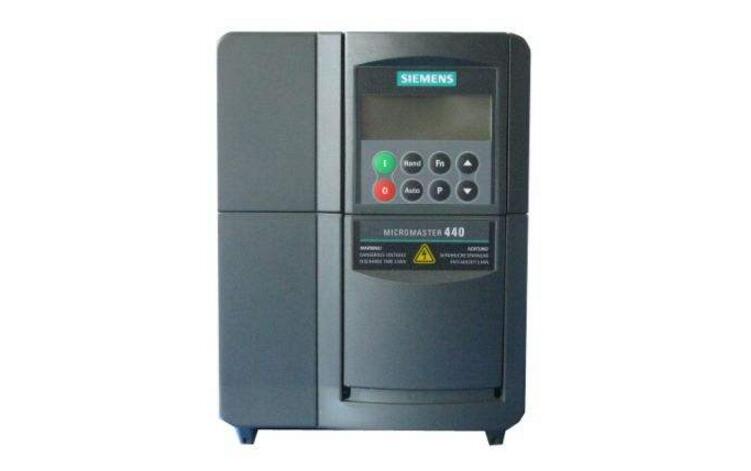
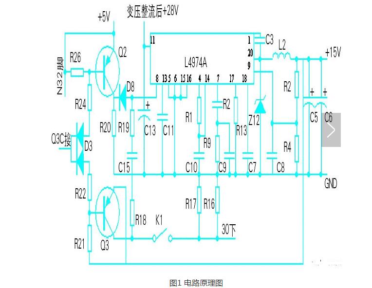
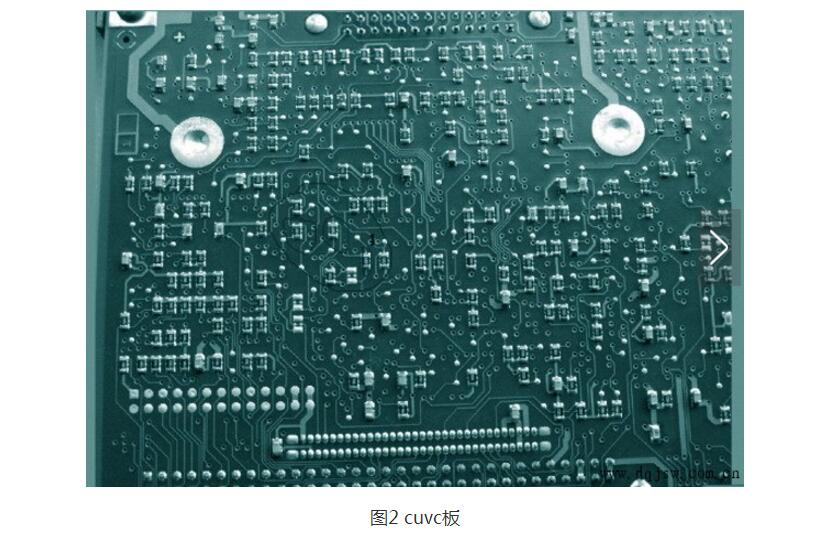
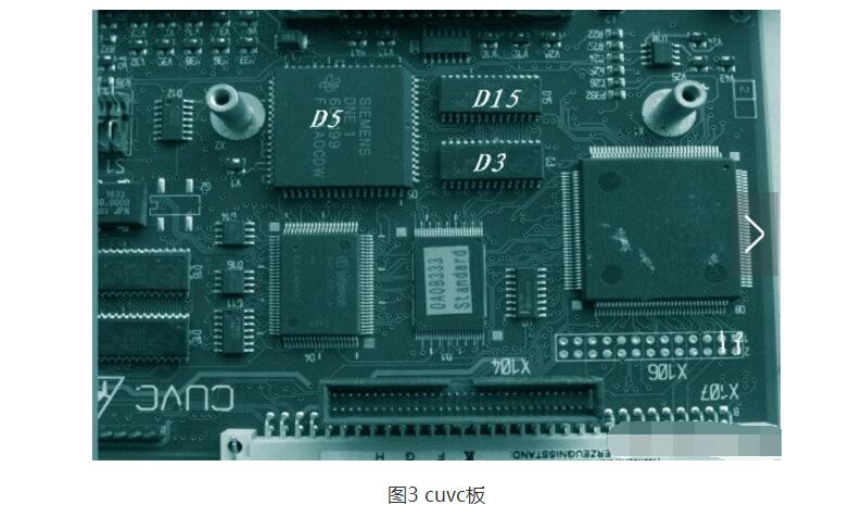
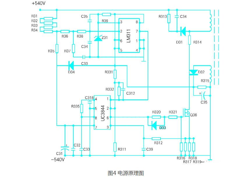
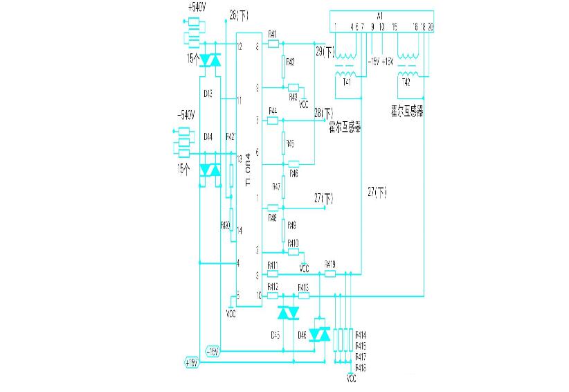
Siemens inverter is a well-known inverter brand developed, produced and sold by Siemens AG of Germany. It is mainly used to control and regulate the speed of three-phase asynchronous motor. With its stable performance, rich combination of functions, high-performance vector control technology, low speed and high torque output, good dynamic characteristics, superior overload capability, innovative BiCo (internal function interconnection) function and unparalleled Flexibility, occupying an important position in the inverter market. The use of Siemens inverters in the Chinese market was first in the steel industry. However, at the time, the motor speed regulation was mainly based on DC speed regulation. The application of frequency converters was still an emerging market, but with the continuous development of electronic components and control theory. The continuous maturity, frequency control has gradually replaced the DC speed control, becoming the mainstream of the drive products, Siemens inverter has achieved super-scale development in this huge Chinese market due to its strong brand effect, Siemens in the Chinese inverter market The successful development should be said to be the perfect combination of Siemens brand and technology. The early Siemens inverters that we can encounter in the Chinese market mainly include SIMOVERTA of current source and SIMOVERTP of voltage source. These inverters have also entered the Chinese market mainly due to the introduction of equipment, and there are still a small amount of use. However, there are mainly MICROMASTER and MIDIMASTER sold in the Chinese market, and the most successful SIMOVERTMASTERDRIVE series of Siemens inverters, which is what we often call the 6SE70 series. It not only provides AC inverters for general-purpose applications, but also provides DC bus solutions for multi-motor transmissions required in special industries such as papermaking and chemical fiber. Of course, Siemens also introduced an ECO inverter that I have technically failed in my opinion but has been quite successful in the market. The technical failure is mainly due to its too high failure rate. The success in the market is mainly because of it. Beyond the Fuji inverter to become the first brand in the Chinese market. The main models of Siemens in the Chinese market are the MM420 and MM440.6SE70 series. There are many setting parameters of the inverter, and each parameter has a certain range of selection. In use, it is often encountered that the inverter cannot work normally due to improper setting of individual parameters. Control mode: speed control, torque control, PID control or other means. After taking the control method, it is generally necessary to perform static or dynamic identification according to the control accuracy. The lowest operating frequency: that is, the minimum running speed of the motor. When the motor runs at low speed, its heat dissipation performance is very poor. When the motor runs at low speed for a long time, the motor will burn out. At low speeds, the current in the cable also increases, which can also cause the cable to heat up. The highest operating frequency: the general frequency of the inverter to 60Hz, and some even to 400 Hz, the high frequency will make the motor run at high speed. For ordinary motors, the bearings can not run for a long time at the rated speed, and the rotor of the motor is Can withstand such centrifugal force. Carrier frequency: The higher the carrier frequency setting, the higher the higher harmonic component, which is closely related to the length of the cable, the heating of the motor, and the heating of the cable heating inverter. Motor parameters: The inverter sets the power, current, voltage, speed and maximum frequency of the motor in the parameters. These parameters can be directly obtained from the motor nameplate. Frequency hopping: At a certain frequency point, resonance may occur, especially when the whole device is relatively high; when controlling the compressor, avoid the surge point of the compressor. We know that the synchronous motor speed expression of the AC motor is: n=60f(1-s)/p(1) In the middle n———the speed of the asynchronous motor; F———the frequency of the asynchronous motor; s———motor slip rate; p———The number of poles of the motor. It can be seen from equation (1) that the rotational speed n is proportional to the frequency f, and the rotational speed of the motor can be changed by changing the frequency f. When the frequency f is varied within the range of 0 to 50 Hz, the motor rotational speed adjustment range is very wide. The frequency converter achieves speed adjustment by changing the frequency of the motor power supply, and is an ideal high-efficiency, high-performance speed control means. Different types of inverters from Siemens, users can choose different types of inverters according to their actual process requirements and application occasions. Pay attention to the following points when selecting the inverter: 1. Select the inverter according to the load characteristics. If the load is a constant torque load, you need to select Siemens mmv/mdv and mm420/mm440 inverters. If the load is a fan or a pump type load, Siemens 430 inverter should be selected. 2. When selecting the inverter, the actual motor current value should be used as the basis for the inverter selection. The rated power of the motor can only be used as a reference. In addition, it should be fully considered that the output of the inverter is rich in high-order harmonics, which will deteriorate the power factor and efficiency of the motor. Therefore, compared with the power frequency grid power supply, the motor current will increase by 10% and the temperature rise will increase by about 20%. Therefore, this situation should be taken into consideration when selecting the motor and the inverter. Appropriate margin should be left to prevent the temperature rise from being too high and affect the service life of the motor. 3. If the inverter is to run with a long cable, measures should be taken to suppress the influence of the long cable to the ground coupling capacitor to avoid insufficient output of the inverter. Therefore, the inverter should be amplified by one or two gears or an output reactor at the output of the inverter. 4. When the inverter is used to control several motors in parallel, it is necessary to consider the total length of the cable from the inverter to the motor within the allowable range of the inverter. If the specified value is exceeded, the two gears should be amplified to select the inverter. In addition, in this case, the control mode of the inverter can only be v/f control mode, and the inverter cannot realize overcurrent and overload protection of the motor. A fuse is added to each motor side for protection. 5, for some special applications, such as high ambient temperature, high switching frequency, high altitude, etc., this will cause the derating of the inverter, the inverter needs to enlarge the first gear selection. 6. When using a frequency converter to control a high-speed motor, because the reactance of the high-speed motor is small, more high-order harmonics are generated. These higher harmonics will increase the output current of the inverter. Therefore, when selecting a frequency converter for a high speed motor, it should be slightly larger than the inverter of a normal motor. 7. When the inverter is used for a pole-changing motor, pay full attention to the capacity of the inverter so that its maximum rated current is below the rated output current of the inverter. In addition, when performing the pole number conversion during operation, the motor should be stopped first. Otherwise, the motor will be idling, which will cause damage to the inverter. 8. When driving the explosion-proof motor, the inverter has no explosion-proof structure, and the inverter should be set outside the dangerous place. 9. When the inverter is used to drive the gear reduction motor, the scope of use is restricted by the lubrication method of the rotating part of the gear. When the lubricating oil is lubricated, there is no limit in the low speed range; in the high speed range exceeding the rated speed, there is a danger that the lubricating oil will be used. Therefore, do not exceed the maximum speed tolerance. 10. When the inverter drives the wound rotor asynchronous motor, most of the existing motors are used. The winding motor has a lower impedance of the winding motor winding than a conventional squirrel cage motor. Therefore, an overcurrent trip due to ripple current is prone to occur, so select a converter that is slightly larger than the normal capacity. Generally, the winding motor is mostly used in the case where the flywheel torque gd2 is large, and more attention should be paid when setting the acceleration/deceleration time. In order to make a preliminary judgment on the quality of the inverter, we can first do a static test on it, mainly for the detection of the DC intermediate circuit and igbt, and use a multimeter to check whether the internal fuse is blown, the capacity of the intermediate filter capacitor and Whether it is breakdown, whether the igbt freewheeling diode is damaged or not. Because the same type of alarm can be caused by the bottom plate, cuvc board, and communication board, do not blindly judge when the fault is found, causing cumbersome work and waste of time. Siemens inverter "e" alarm (according to the analysis of the reasons: the bottom plate (15v too low), cuvc board (5v voltage is not transmitted to the designated location, cuvc board has a short circuit fault). (1) Siemens inverter 6se7023-4ta61-z failure phenomenon: control panel pmu LCD display shows "e" alarm Processing situation: â— Replace the cuvc board to power on, the LCD still displays the “e†alarm, indicating that the cause of the fault is not on the cuvc board but on the bottom board; â— Check the bottom plate, use the multimeter to measure the voltage of the bottom plate, and find that 15v is obviously low. Check the soft start voltage of 8 feet is 0.5v (normal value is 3.85v). Check 5v normal, q2 trigger voltage is normal, use q10 to test q2 faulty change After the new voltage returns to normal, 15v output is normal, restore the inverter wiring, input parameters, start the inverter running normally, as shown in Figure 1. (2) Siemens inverter 6se7016-1ta61-z failure phenomenon: control panel pmu LCD display "e" alarm Handling situation: replace the cuvc board to send power on (see Figure 2), everything is normal, indicating that the fault is on the cuvc board, and the three 1kΩ resistors related to the test are measured, and one has changed value, and it returns to normal after being replaced. (3) Siemens inverter 6se7021-0ta61-z failure phenomenon: control panel pmu LCD display shows "e" alarm Treatment situation: Check the bottom plate 15v is not normal, seriously too small, the bottom plate has obvious overheating phenomenon, disconnect the 15v load, return to normal, obviously the fault is in its load, after being investigated as the rear mos tube short circuit, the mos tube and After the parallel voltage regulator is replaced, the voltage is restored and the re-powered test machine is normal. (4) Siemens inverter 6se7016-1ta61-z failure phenomenon: control panel pmu LCD display shows "e" alarm Processing situation: Replace the cuvc board failure disappears, indicating that the fault is on the cuvc board, using the multimeter resistance file to measure 1, 2 points (5v power supply end) resistance value 320ω (normally 486ω) proves that the circuit has a short circuit, after checking d5 There are two feet directly broken down, use the heat gun to remove the d5, replace it with a new one (the welding must be careful, do not have a short circuit or open circuit) to re-send the test machine, completely return to normal (see Figure 3). Siemens inverter black screen general failure causes (power supply damage, igbt short circuit caused by internal insurance burned). (1) 6se7023-4tc61-z failure phenomenon: no display on the control panel pmu LCD Processing situation: Using the meter to measure the internal igbt has been severely short-circuited, causing the internal insurance has been blown to lose power, replace the igbt and repair the trigger circuit to re-power, everything is normal. (2) 6se7016-1ta61-z failure phenomenon: no display on the control panel pmu LCD Processing situation: use external 24v power supply test machine, the screen display is normal, then use the multimeter to measure low-voltage AC output, no voltage indicates fault at the power supply, test uc3844 (6) foot pulse output is normal, no to q36 gate, measured by table r321 After the 28ω is changed to infinity, the test machine is replaced and the fault disappears. See Figure 4. “008†is the start-up blocking alarm, the inverter can't start. The cause of the fault: After the power is turned on, the inverter tests its test point. If the condition is reached, the output signal of the cuvc board will short-sea the charging resistor with the parallel relay to the inverter. Run it with a larger current, otherwise it will display "008" on the screen and it will not start. (1) 6se7023-4ta61-z failure phenomenon: control panel pmu LCD display "008" alarm Processing situation: 30 (below) is 008 detection point (normally 15v), measurement 30 (lower) has no 15v, k1 has been closed, check q3 emitter has 15v base voltage normal, suspected q3 damage, after new power transmission, Everything is fine (see Figure 1). (2) Siemens inverter 6se7022-4ta61-z failure phenomenon: control panel pmu LCD display "008" alarm Treatment situation: Replace the cuvc board is normal, indicating that the fault is in cuvc, and it is found that the r652 and r658 connected with it are damaged. After the replacement, the test is normal (see Figure 2). 6se7016-1ta61-z failure phenomenon: control panel pmu LCD display "f002" voltage is too low alarm Processing situation: Check the bus line DC 540v is normal, indicating that the bottom plate voltage detection system is faulty. After detecting the DC bus 540v voltage through the resistor series through tl084, the signal is sent to the cuvc board. If the detection voltage is lower than the value set by parameter p071, the motor will be stopped. The alarm is issued, and the voltage of the multimeter is measured by the multimeter voltage meter (the normal value is 2.38v), and then 30 resistors connected in series with the resistance file are found to have two signals that cannot be transmitted due to the corrosion being broken. After the resistor is replaced, the power is transmitted. The test is all normal (see Figure 5). The common faults of the inverter can be divided into two types of faults: external fault and internal fault of the inverter according to the type of fault. In the case of external fault, attention should be paid to detecting the external parameters of the inverter, external power supply, motor, etc. The internal faults of the inverter are divided into two aspects: soft fault and hardware fault. The external faults of the inverter are mainly of the following types: (1) If the parameter setting is wrong, the parameters set in the inverter need to match the driven motor. If the inverter parameter is set incorrectly or the setting is wrong, the inverter will not start normally. (2) External wiring failure, the external wiring of the inverter will cause problems such as disconnection and plug damage after long-term use, which will affect the normal operation of the inverter. (3) There is a problem with the external power supply of the inverter. When the external power supply of the inverter has problems such as “undervoltage, overvoltage, overcurrent, overfrequencyâ€, the Siemens inverter will not operate normally. (4) Overload, the overload of the Siemens inverter is mainly caused by the short acceleration time, excessive braking or low grid voltage. This problem can be solved by extending the motor start acceleration time and extending the motor braking time. The overload caused by the motor can focus on checking whether the motor is stuck or the like. (5) Overcurrent, which causes the external overcurrent problem of the Siemens inverter may be caused by a sudden change in the motor load, causing a large impact, and the insulation of the motor or the power supply cable is damaged and short-circuited. The software and hardware faults of the Siemens inverter are mainly aimed at the Siemens inverter itself. Because the Siemens inverter needs to withstand high voltage and high current for a long time, its internal hardware (control panel type control components, IGBT and other power components) The burning damage of the machine, which affects the normal operation of the Siemens inverter When the Siemens inverter fails, first check the alarm information displayed on the digital tube on the Siemens inverter, and view the alarm description of the Siemens inverter for the alarm information to locate the fault of the Siemens inverter. If you directly inspect a faulty Siemens inverter, you must first use a multimeter to measure the Siemens inverter at the beginning of the power-on inspection. Use a multimeter to check the power components such as the rectifier bridge and IGBT module in the Siemens inverter and check whether there are obvious burn marks in the Siemens inverter. When using a multimeter to check the power components, connect the multimeter to the 1K resistor, connect the black meter to the DC (-) pole of the Siemens inverter, and then use the red meter of the multimeter to connect the three inputs of the Siemens inverter. The output is used to measure the resistance. The measured resistance should be between 5-10K and the input and output phases should be consistent with each other. The three-phase resistance at the output should be slightly smaller than the input resistance. The (-) measurement is completed. After the resistance measurement, continue to place the black test pen in the (+) test to continue the three-phase measurement. The measurement method is consistent with the above. If the measured resistance value is normal, there is no charge or discharge phenomenon, indicating that the Siemens inverter can be powered on, if not This means that the power components of the Siemens inverter need to be replaced with the components that have problems in the measurement. In particular, the Siemens inverters must be powered directly without any obvious burning marks on the power components in the Siemens inverters. After the initial measurement of the Siemens inverter is completed, the Siemens inverter needs to be powered on. Take the MM4 inverter in the Siemens inverter as an example: (1) After the power-on, the digital tube on the Siemens inverter shows the fault of F231, which means that there is a problem with the power driver board or the main control board of the Siemens inverter, you can replace the power driver board in the Siemens inverter or It is the main control board to test. (2) If the panel is not displayed after the Siemens inverter is powered on or the indicator under the panel is not lit, it means that there is a problem in the rectification and power supply part of the Siemens inverter. The power supply part of the Siemens inverter should be tested. Use a multimeter to detect the rectifier diode in the rectifier section of the Siemens inverter, and find that the diode with the problem can be replaced directly to solve the problem. (3) If the Siemens inverter is powered on (------), most of them mean that there is a problem with the main control board in the Siemens inverter, which can be solved by replacing the main control board of the Siemens inverter. The cause of such failures is mainly due to the large amount of clutter in the external access line of the Siemens inverter, which causes the resistance and capacitance of the main control board of the Siemens inverter to be damaged after impact. In addition, In the process of working with the Siemens inverter, a large amount of heat is generated. For example, the heat dissipation of the main control board of the Siemens inverter may cause the electronic components on the main control board to burn out. (4) After the Siemens inverter is powered on, the overcurrent alarm will be displayed on the Siemens inverter whether it is running at no load or with load. When such a fault occurs, it generally means that the IGBT power components in the Siemens inverter are damaged. The power components and drive parts of the Siemens inverter should be measured in detail to detect the problematic power and drive components. After replacing the new components, the power can be re-powered after detailed measurement. If there is a problem in the drive part, it will result in The newly replaced IGBT in the Siemens inverter is burned again after power-on. The cause of such failures is mainly due to the fact that the Siemens inverter has multiple overloads during the use process or the Siemens inverter has been subjected to large voltage fluctuations for a long time, which causes the devices in the Siemens inverter to burn out. It is necessary to test the external circuit of the Siemens inverter to detect whether the motor is normal, and install a voltage protection device at the incoming end of the Siemens inverter to avoid the Siemens inverter burning. (5) In the process of using a Siemens frequency converter, there is often a “stop†without warning. After restarting, it may be normal. After the Siemens inverter is removed, all the devices are found to be unable to find the problem. After a long period of observation after the Siemens inverter is powered on, it is found that during the operation of the Siemens inverter, the main contactor may have abnormal suction and contact during operation, which may cause the Siemens inverter to be unable to work for a period of time. Keeping the pull-in state and causing power failure, jumping and other problems, after disassembling the main contactor of Siemens inverter, the main cause of this fault is that the switching power supply and the main contactor wire package in the Siemens inverter are all the way. The filter capacitor leaks, resulting in a low voltage, which makes it impossible to properly pick up. For example, the problem of high supply voltage can cover up the past and when the voltage is low, the problem will be more obvious. After analyzing the common faults of Siemens inverters, it is found that the proportion of damage of power components in Siemens inverters is not high, but the proportion of damage of control devices such as resistors and capacitors is high. Pay attention when troubleshooting. SHENZHEN CHONDEKUAI TECHNOLOGY CO.LTD , https://www.szsiheyi.com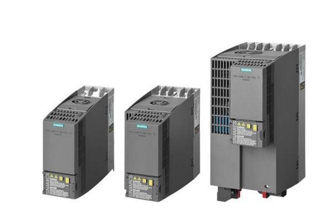

Introduction to the most common fault analysis and processing methods of Siemens inverters
Siemens frequency converter overview