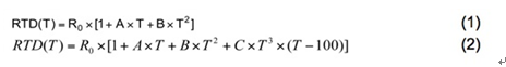
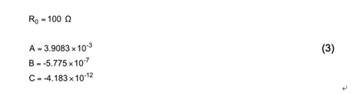
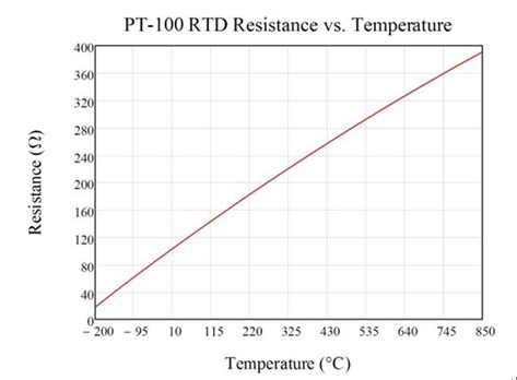
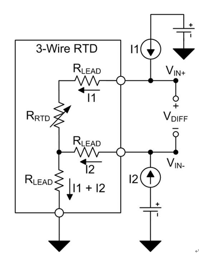
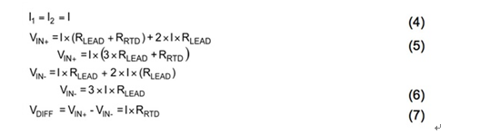
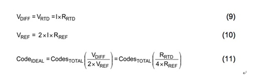
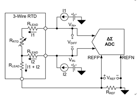
Many medical, process control, and industrial automation applications require precise temperature measurements to perform their functions. Resistive temperature detectors (RTDs) are commonly used as sensing elements in these accurate temperature measurements because of their wide temperature measurement range, good linearity, and excellent long-term stability and repeatability. The RTD is a sensing element made of metal with predictable resistance over the operating temperature range. The resistance of the RTD sensor can be calculated by injecting current through the RTD and measuring the voltage. The RTD temperature can then be calculated based on the relationship between RTD resistance and temperature. This article discusses the principles and advantages of a proportional three-wire measurement system. Pt100 RTD Overview The Pt100 RTD is a platinum RTD sensor that delivers superior performance over a wide temperature range. Platinum is a precious metal that has the highest resistivity as a commonly used RTD material and enables small-sized sensors. An RTD sensor made of platinum is sometimes referred to as a platinum resistance thermometer or PRT. The Pt100 RTD has an impedance of 100 Ω at 0 °C, and a temperature change of about 1 °C causes approximately a resistance change of 0.385 Ω. When at the limit of the available temperature range, the resistance is 18.51 Ω (at -200 ° C) or 390.48 Ω (at 850 ° C). Higher value resistive sensors such as the Pt1000 or Pt5000 can be used to increase sensitivity and resolution. The Callendar Van-Dusen (CVD) equation interprets the relationship between the resistance characteristics of an RTD and the temperature (T, in degrees Celsius). When the temperature is positive, the CVD equation is a second-order polynomial, as shown in equation (1). When the temperature is negative, the CVD equation is extended to the fourth-order polynomial shown in equation (2). The CVD coefficients (A, B and C) are specified in the European IEC-60751 standard. Equation (3) shows these coefficient values. R0 is the resistance of the RTD at 0 °C. Figure 1 plots the change in Pt100 RTD resistance as the temperature increases from -200 °C to 850 °C. Figure 1: Pt100 RTD resistance when the temperature is increased from -200 °C to 850 °C Three-wire RTD Three-wire RTD configurations are popular because they strike a balance between cost and accuracy. In the recommended three-wire configuration, an excitation current (I1) can generate a voltage potential across the RTD element. At the same time, another excitation current (I2) is injected to cancel the resistance of the RTD lead (RLEAD) from the final measured value, as shown in Figure 2 and Equation (4-7). Figure 2: Three-wire RTD with wire resistance RTD measurement circuit configuration The differential RTD voltage VDIFF is typically converted by an analog to digital converter (ADC) and passed to the processor for interpretation. The ADC compares the input voltage to a reference voltage, VREF, to produce a digital output. Figure 3 shows a three-wire RTD measurement circuit using a discrete external reference voltage. Equation (8) defines the final conversion result based on the total number of digital codes, the RTD resistance, the magnitude of the field current, and the reference voltage. This example assumes that the ADC has a full-scale range of ±VREF. As shown in the figure, errors due to the magnitude of the reference voltage and field current, noise, and temperature drift directly cause conversion errors. Figure 3: Three-wire RTD circuit with external reference Placing the RTD and ADC in a proportional configuration (Figure 4) results in a more accurate circuit configuration for a three-wire RTD system. In a proportional configuration, the field current flowing through the RTD can be returned to ground through the low side reference resistor RREF. The voltage potential VREF formed across the RREF is supplied to the positive and negative reference pins (REFP and REFN) of the ADC. The voltage drop across the RTD and RREF resistors is generated by the same field current (Equation 9 and Equation 10). Therefore, changes in the field current are reflected in both the RTD differential voltage and the reference voltage. Since the ADC output code indicates the relationship between the input voltage and the reference voltage, the final conversion result can be converted to the ratio of the RTD resistor to the RREF resistor, not depending on the value of the reference voltage or field current (Equation 11). Therefore, if the excitation current is perfectly matched and does not affect the final conversion result, the error due to the magnitude of the excitation current, temperature drift, and noise can be eliminated. In addition, the proportional configuration also helps to reduce the effects of external noise, as this noise is also eliminated. Figure 4: Proportional three-wire RTD circuit Excitation current source mismatch error The two excitation currents must be equal to each other to achieve the desired transfer function (Equation 11). The field current mismatch changes the ideal system transfer function because it reduces the effectiveness of the lead resistance cancellation. When an excitation current is reduced or increased to the limit specified by the mismatch specification, the transfer function has the most severe effect. This is explained in equation (12), where Δ represents the excitation current mismatch. A mismatch in I2 can result in a change in the ideal transfer function (Equation 13). By comparing the calculation result of equation (13) with the ideal transfer function of equation (11), equation (14) can calculate the gain error caused by the excitation current mismatch. If it is specified that the field current mismatch is expressed by %FSR, the gain error can be calculated as shown in equation (15). Gain errors due to field current mismatch can be eliminated by standard gain calibration. However, the field current mismatch typically drifts with temperature, which requires complex calibration to correct. to sum up In this article we describe the benefits of three-wire RTD, lead resistance cancellation, and building a proportional three-wire RTD system. We point out that when the proportional RTD configuration eliminates the error from the initial accuracy of the field current, the mismatch between the two field currents still causes a gain error.
Products of Accessories LED Display, LED electronic display screen integrates microelectronics technology, computer technology, and information processing. It has the advantages of bright colors, wide dynamic range, high brightness, long life, stable and reliable work. LED displays are widely used in commercial media, cultural performance markets, stadiums, information dissemination, press releases, securities trading, etc., to meet the needs of different environments. which include Flat Cable, Signal Cable, Net Cable, Power Cable, Screws, Magnets etc.We Jongsun LED is specialized manufacturer from Shenzhen China, which focusing on the research and development, production, sales and engineering services of terminal LED Displays. We have the perfectly after-sales and 7x24hours technical support. Looking forward your cooperation!
Accessories Of Led Display,Single Red Led Module,Red Led Display Module,Smd Indoor Led Display Module Shenzhen Jongsun Electronic Technology Co., Ltd. , https://www.jongsunled.com