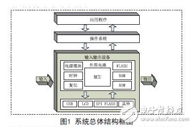
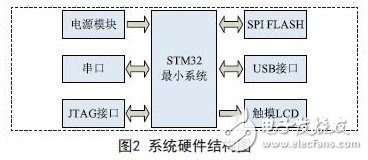
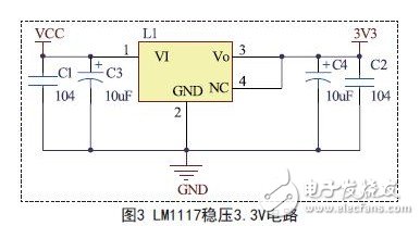
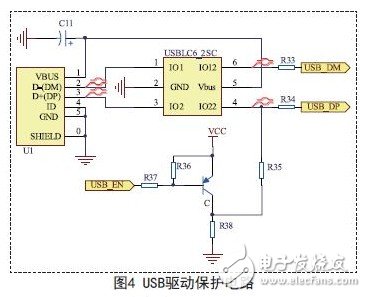
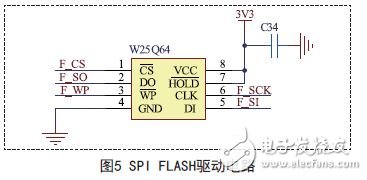
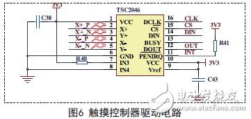
1 Introduction In recent years, with the popularization of digital cameras, a digital photo frame has emerged as a core product for the preservation, playback and browsing of digital photos. It has been favored by the market for its unique design concept and wonderful appreciation effect. The digital photo frame adopts the appearance of the traditional ordinary photo frame, and replaces the middle photo part of the traditional ordinary photo frame with the liquid crystal display, and is equipped with a power supply, a controller, a storage medium and the like, and can directly display the digital photo. At the same time, the digital photo frame can also display different photos in the same photo frame, which solves the defect that the computer needs to be used to view the digital photos, and provides a better platform and space for people who are enjoying digital photos and photos. . Based on this, the system designed a digital photo frame based on RT-Thread and STM32. The system adopts STM32 as the main control chip, and uses the embedded RT-Thread operating system with open source code and the human-computer interaction interface μC/GUI to establish a digital photo frame system. The system mainly realizes the functions of JPEG format pictures on the touch screen, USB host read function, SPIFLASH storage and so on. 2. Overall system design The system consists of embedded processor, peripheral device, embedded operating system and application software. The system uses embedded RT-Thread and embedded microcontroller STM32 as the core platform, establishes human-computer interaction interface through μC/GUI, uses the USB host read function to write picture and font files to external SPI FLASH, and uses the file system to read pictures. The file is processed by the image decoding algorithm and displayed on the touch screen to complete the browsing function of the image by touch. The overall structure of the system is shown in Figure 1. 3. System hardware design The system uses STM32 as the main hardware platform, and the overall hardware structure of the system is shown in Figure 2. The system hardware mainly consists of power module, STM32 minimum system, JTAG download debugging interface, USB driver circuit, SPI FLASH driver module, touch LCD driver circuit and so on. 3.1 Power Module In this system, the microcontroller and its peripheral circuit driver module need 3.3V power supply. The power battery selected by the system is 3.7V, which needs to provide 3.3V voltage through the voltage regulator chip. For the 3.3V voltage, the National Semiconductor's LM1117 regulator chip outputs 3.3V, and the LM1117 provides current limiting and thermal protection. The circuit contains a Zener-adjusted bandgap reference voltage to ensure an output voltage accuracy of ±1%. A tantalum capacitor of at least 10uF is required at the output to improve transient response and stability. The 3.3V circuit of the LM1117 regulator chip output is shown in Figure 3. 3.2 USB drive circuit The STM32 chip integrates USB peripherals to reduce the design burden of the USB circuit. The system is designed with a USB interface circuit and an ESD protection circuit. 3.2.1 USB interface circuit In the USB interface circuit, the USB pull-up voltage is connected to the D+ to realize USB full-speed communication, and the triode is a switch function. When the switch is turned on, the PC starts enumerating the USB storage device. The USB VCC pin does not have power on the board, and the USB device is powered by the PC. 3.2.2 ESD protection circuit Using STMicroelectronics' USBLC6-2P6, the chip fully balances the D+/D- signals of the USB, and the matching tolerance of the I/O interface to the ground is only 0.04pF, which is completely within the tolerance of USB 2.0 up to 1pF. If ESD occurs on the USB data line, the ESD protection function of the chip will lead the current to the ground. To ensure the highest performance of ESD protection, the data line adopts the rail-to-rail protection topology. In order to improve the output power, the VCC line is clamped. Protection structure. The schematic diagram of the USB drive protection circuit is shown in Figure 4. 3.3 SPI FLASH drive circuit The system adopts SPI serial flash memory chip W25Q64, which has the advantages of simple circuit design and fast data reading speed, which can reduce system circuit switching noise, reduce system power consumption and development cost. Its application circuit is shown in Figure 5. 3.4 LCD touch drive circuit The system's touch controller is TSC2046. The TSC2046 is a four-wire resistive touch screen controller. The core is a 12-bit successive approximation A/D converter with sample and hold function. This system drives the TSC2046 controller through the SPI interface of STM32. The typical drive circuit is shown in Figure 6.
Smart RGBW bulbs add RGB colorful light based on the traditional warm light, they are suitable for home, bars and offices.
Now two control ways of Smart RGBW Bulb are for choice, 2.4G remote control, and bluetooth mesh phone control. Users can choose the light mode according to time, scene and mood, adjust the brightness, color temperature and light color according to the intention. Using energy-saving and high-quality LED light beads, the light source is stable without stroboscopic, effective life can be more than 20000 hours. Bulbs can meet international quality standards and pass tests by TUV Rheinland. EMC, RED, LVD, ROHS, REACH, ERP, FCC certification can be provided.
The control software and hardware of bulb are independently developed by our team, based on two different communication protocols: 2.4G wireless and Bluetooth Mesh.
The remote control is designed exclusively, using 2.4G wireless technology, the advantage of 2.4G is the low signal frequency, small attenuation when propagating in air or obstacles, control distance is 20m. Low power consumption, only needs 4 AA batteries to be used for two years.
The App is developed on the most advanced Bluetooth Mesh technology. [LinkupHome" App can be downloaded from the App store or Google Player, then you can control our product without any complicated steps. The App is stable, easy control and multifunctional.
Smart Technology- Bluetooth Mesh
The advantages of Bluetooth Mesh are fast connect, low power consumption, no password required and Ad-Hoc Network. The Mesh function provides multi-to-multi-transmission between devices, and especially improves the communication capability of building large-scale network coverage. It is suitable for Internet of things solutions such as building automation and wireless sensor network that need to allow tens of thousands of devices to transmit in a reliable and secure environment.
Product Parameters
Control distance: 20m
Product dimension: Dia66mm * H122mm
Material: PC & Aluminum & Nylon
Working Voltage: 100-240V
Frequency: 50-60Hz
Color Temperature: RGB+Warm White (3000K)
LED Power: 9.5W (710lm)
Base Type: E27/E26/B22 available
Warranty: 2 Years
Certification: CE(EMC,RED), ROHS,FCC
Smart RGBW Bulb Smart RGBW Bulb,RGBW Light,Smart RGBW Spotlight,Smart RGBW Solar Lamp Ningbo Homey Photoelectric Technology. Co., Ltd , https://www.linkuphome.com