DC power supply testing and specification
**1.0 Purpose**
This document establishes the electrical performance specification test procedure for ITECH DC power supplies. It defines the test items, testing methods, and criteria for evaluating the electrical performance of DC power supplies. The goal is to provide a consistent and reliable basis for all performance tests, ensuring that the actual technical performance of the DC power supply meets design specifications, customer requirements, international standards, and quality expectations.
**2.0 Scope of Application**
This standard applies to the performance specification testing of all DC power supplies produced by the company.
Exceptions:
1. If the customer has specific requirements or specifications that differ from this standard, the tests should be conducted according to the customer’s stated requirements.
2. In case of conflict between this standard and applicable national or international standards, the latter shall take precedence.
**3.0 Reference Documents**
- 3.1 Agilent Power Test Standard
- 3.2 Tektronix Power Test Standard
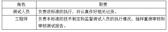
**4.0 Responsibilities**
The responsibilities are outlined in the following diagram:
**5.0 Definitions**
No definitions are provided in this section.
**6.0 Workflow**
6.1 R&D department fills out the “Product Delivery Test Notice†→ Electrical Performance Test → Safety and Electromagnetic Compatibility Test → Reliability Test → Test Report
6.2 Electrical Performance Specification Test
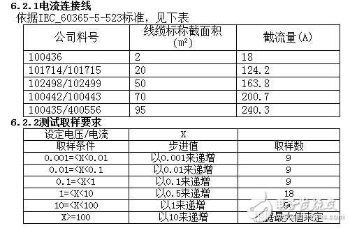
**6.3 Set Value and Readback Value Accuracy Test (Voltage)**
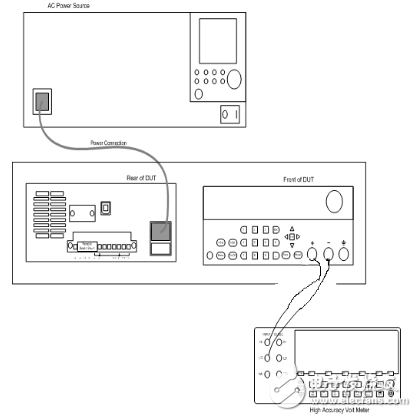
**6.3.1 Test Procedure**
1. Connect the device as shown in the diagram. Adjust the AC source output voltage according to the tested power supply's input voltage (110V/220V).
2. Set the digital multimeter to:
a) DC Voltage
b) Automatic Range
3. Set the DUT (Device Under Test):
a) Current Setting: 0.02A
b) Initial Voltage Setting: 0.1V
4. Warm up the unit for 20 minutes.
5. Turn on the DUT and ensure it is in the ON state.
6. Record the multimeter reading as the actual measured value. Calculate the set value error using this value and the set voltage. Record the data.
7. Record the readback value of the DUT, calculate the readback error based on the actual measured value, and record the data.
8. Adjust the DUT voltage according to its rating and Table 6.2.2.
9. Repeat steps 6–8 until the DUT reaches 100% FS (Full Scale).
10. Complete the set and readback voltage accuracy test, then turn off all test equipment.
**6.3.2 Test Connection Diagram**
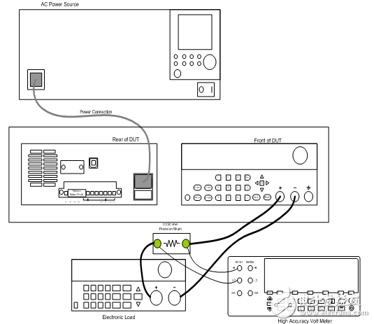
**6.4 Set Value and Readback Value Accuracy Test (Current)**
**6.4.1 Load CV Mode**
1. Connect the device as shown above. Adjust the AC source output voltage according to the tested power supply's input voltage (110V/220V).
2. Set the digital multimeter to:
a) DC Voltage
b) Automatic Range
3. Set the electronic load to:
a) CV mode
b) Set Voltage: 3V
4. Set the DUT:
a) Output Current: 0.1A
b) Output Voltage: 20% FS (3V)
5. Warm up the unit for 20 minutes.
6. Turn on the DUT and ensure it is in the ON state.
7. Record the multimeter reading as the sampling voltage (Us). Calculate the actual current using Im = Us/Rs (shunt resistor), and compute the set error based on the actual measured current and the set current. Record the data.
8. Read the DUT’s readback current, calculate the readback error using the actual measured current, and record the data.
9. Adjust the DUT voltage according to its rating and Table 6.2.2.
10. Repeat steps 7–9 until the DUT reaches 100% FS of current.
11. Complete the set and readback current accuracy test, then turn off all test equipment.
**6.4.2 Load CC Mode**
1. Connect the device as shown above. Adjust the AC source output voltage according to the tested power supply's input voltage (110V/220V).
2. Set the digital multimeter to:
a) DC Voltage
b) Automatic Range
3. Set the electronic load to:
a) CC mode
b) Set Current: Load enters short circuit mode
4. Set the DUT:
a) Output Current: 0.1A
b) Output Voltage: 20% FS (3V)
5. Warm up the unit for 20 minutes.
6. Turn on the DUT and ensure it is in the ON state.
7. Record the multimeter reading as the sampling voltage (Us). Calculate the actual current using Im = Us/Rs (shunt resistor), and compute the set error based on the actual measured current and the set current. Record the data.
8. Read the DUT’s readback current, calculate the readback error using the actual measured current, and record the data.
9. Adjust the DUT voltage according to its rating and Table 6.2.2.
10. Repeat steps 7–9 until the DUT reaches 100% FS of current.
11. Complete the set and readback current accuracy test, then turn off all test equipment.
**6.4.3 Test Connection Diagram**
IDC Type
IDC Type
HuiZhou Antenk Electronics Co., LTD , https://www.atkconn.com