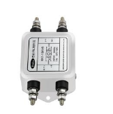
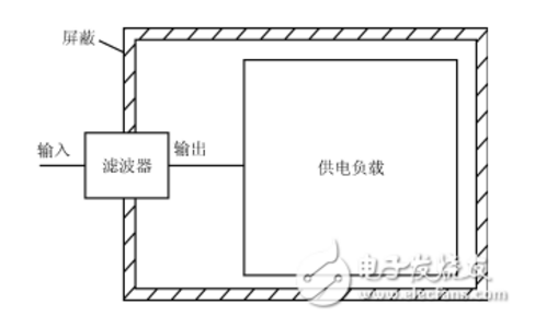
This article mainly introduces the classification and selection principles of power supply filters, so that you no longer have any doubts about choosing power supply filters. A filter, as the name suggests, is a device that filters waves. The filter can effectively filter out the frequency point of a specific frequency in the power line or the frequency other than the frequency point to obtain a power signal of a specific frequency, or eliminate a power signal of a specific frequency. Power filtering can obtain smooth DC power or filter out high-order harmonic signals of AC power. Filtering is generally used to filter interference signals and retain useful information. According to the filter frequency response characteristics, low-pass filters are generally used to filter out high-frequency interference; high-pass filters are generally used to filter out low-frequency interference or AC coupling; band-pass filters are generally used to pass effective signals with limited bandwidth; band rejection Filters are generally used to filter out interference signals of specific frequencies, such as: 50Hz notch filters; all-pass filters are generally used for phase correction filtering. The power filter is a filter circuit composed of capacitors, inductors and resistors. The filter can effectively filter out the frequency point of a specific frequency in the power line or the frequency other than the frequency point to obtain a power signal of a specific frequency, or eliminate a power signal of a specific frequency. According to the signal processed: There are two types of analog filters and digital filters. According to the frequency band of the passed signal: Low-pass filter: it allows low-frequency or DC components in the signal to pass, and suppresses high-frequency components or interference and noise; High-pass filter: it allows the high-frequency components in the signal to pass and suppresses low-frequency or DC components; Band pass filter: It allows signals in a certain frequency band to pass, and suppresses signals, interference and noise below or above the frequency band; Band stop filter: It suppresses signals in a certain frequency band and allows signals outside the frequency band to pass. According to the components used: Passive filter: a power filter composed of only passive components. It is constructed using the principle that the reactance of capacitors and inductance components changes with frequency. The advantages of this type of filter are: the circuit is relatively simple, does not require a DC power supply, and has high reliability; the disadvantage is: the signal in the passband has energy loss, the load effect is more obvious, and the use of inductive components is likely to cause electromagnetic induction. When L is large, the size and weight of the filter are relatively large, which is not applicable in the low frequency domain. Active filter: It is composed of passive components and active devices. The advantages of this type of power filter are: the signal in the passband not only has no energy loss, but also can be amplified, the load effect is not obvious, the mutual influence is small when multi-stage is connected, and the simple method of cascade is easy to form a high-end Filter, and the filter is small in size, light in weight, and does not require magnetic shielding; the disadvantage is that the passband range is limited by the bandwidth of the active device and requires DC power supply. The reliability is not as high as that of passive filters. It is not suitable for occasions with high frequency and high power. According to the placement position: On-board filters and panel filters. The on-board filter is installed on the circuit board, such as PLB and JLB series filters. The advantage of this kind of filter is economy, the disadvantage is that the high frequency filtering effect is not good. The main reasons are: 1. There is no isolation between the input and output of the filter, which is prone to coupling; 2. The ground impedance of the filter is not very low, which weakens the high-frequency bypass effect; 3. The gap between the filter and the chassis A section of the connection will have two undesirable effects: one is that the electromagnetic interference in the internal space of the chassis will be directly induced to this section of the line, and it will be transmitted out of the chassis along the cable, and the filter will be invalidated by the use of cable radiation; the other is that external interference is being affected. Before the on-board filter is filtered, use this line to generate radiation, or directly couple with the circuit on the circuit board, causing sensitivity problems; Panel filters such as filter array boards and filter connectors are generally directly installed on the metal panel of the shielding case. Because it is directly installed on a metal panel, the input and output of the filter are completely isolated, the grounding is good, and the interference on the cable is filtered out on the chassis port, so the filtering effect is quite ideal. There are many kinds of filters, and power filters and signal filters are commonly used in equipment. Other types of power filters for reactive power compensation and microwave frequency filters are not discussed here. 1. Voltage This voltage value requirement is a range, which is the synthesis of steady-state voltage ± ripple voltage. 2. Current The current index is very important, it determines the wire diameter of the winding copper wire and the lead wire of the inductance inside the filter. If you choose a thinner wire, running a large current on the thin wire, such as a small horse-drawn cart, will cause severe heat and even burn. This current is also a range, the maximum value of steady-state current + fluctuating current. 3. Electromagnetic compatibility standard requirements Since it is a filter, the purpose is to filter out some undesired frequency bands, and the filtering effect is generally determined by the intuitive results of EMC test standards and field applications. Especially for power supply filters, it is best to determine which standard the product using this filter needs to pass. According to the different standard requirements, there are also specific test frequency band requirements when selecting. The main indicators of the power filter are the conducted emission CE and the conducted anti-interference CS, and the signal filter mainly depends on the requirements for the undesired input frequency band and the undesired output frequency band in the EMC standard. For example, the rectifier used in induction lamps is a switching state and will have external emission. During EMC testing, the switching frequency and the conduction interference of its high-order harmonic components will be checked. The filter needs to be targeted at these specific frequency bands or frequencies. The point has sufficient filtering effect. 4. Safety standard requirements Readers may find it strange to choose a filter and say what safety standards do? This is because the filter is generally used at the power input terminal and the interface of the board. These parts are the hardest hit areas for safety issues. It is equivalent to the filter itself has undertaken multiple requirements. The focus of safety regulations related to filters are three indicators: insulation withstand voltage, leakage current, residual voltage and residual energy. The insulation strength of LN to ground is tested by the withstand voltage value of the Y capacitor. If the Y capacitor is large, the leakage current will be large, which will easily cause the leakage current in the safety requirements to exceed the standard. Now some manufacturers design it A design with no Y capacitor at the input is adopted (as shown in the figure). In this way, LN to G becomes LN through L1, Cy1, Cy2, G'to G, and G and G'are not connected. If the input terminal is connected to the Y capacitor, that is, Cy1 and Cy2 are placed on the left side of the front R, the insulation withstand voltage setting and the leakage current are positively correlated during the test, and the maximum is not more than 20mA. I have encountered a situation where the filter was almost returned and said the safety of the filter was unqualified. Finally, it was checked that the leakage current was set to 2mA (should be 5mA) at 1500V, and the test instrument alarm was normal. Another problem is the choice of R. There are many manufacturers’ filters that do not install this resistor. After unplugging, touch the power socket within a short period of time. If there is a feeling of being charged, the problem lies in it. This resistor is not installed. This is a power resistor with high withstand voltage and a role of bleeder and discharge. 5. Filter circuit structure The choice of circuit structure and period parameters is the core of the filter, but it is in this part that application engineers often choose with a blind eye. Although it can be used most of the time, they do not know their own or other design methods. , The possibility of wasting resources and burying hidden dangers is greatly increased. This is out of date in the electronics manufacturing industry that requires lean design, from Chinese manufacturing to Chinese creation, and from the growth expectations of junior engineers to senior engineers. The function of the filter is to have different amplification effects on the different frequencies passing through it. It does not attenuate the frequency band within the passband, and attenuates the frequency band outside the passband at the level of tens of dB, so as to achieve the sieve. purpose. But even when the filter adopts different magnifications for the voltage amplitude of different frequencies, the phase of the electromagnetic wave is also changing, because the phase is also related to the frequency, so the selection of the filter structure is still somewhat knowledgeable. There are three commonly used filter structures: a. Butterworth filter: The characteristic is that the magnification in the passband is flat, and in the passband, with the change of frequency, the magnification of the filter basically remains unchanged; but the disadvantage is that the transition section from the passband to the cutoff section is transitional. More gentle. It means that the boundary between the enemy and the friend is not very clear. Some of our friends are also doing the enemy's things, and some of the enemies are also helping us. It is very entangled to kill this part or stay in the organization. If the useful frequency and the interference frequency are very close, the function of this kind of filter is very problematic. b. Chebyshev filter: It can solve the shortcomings of the smooth transition zone of Butterworth. In this form of filter, the transition zone is very steep, even if the useful frequency and the interference frequency are very close, because the transition zone is very close. It is steep, so the difference in the magnification of the two frequency bands before and after the cutoff frequency point is very big. It is easy to distinguish whether it is a friend or an enemy. If it is a friend, it has never done something sorry for us, and if it is an enemy, it has never done a good thing for us. , So friends are drawn into the organization and treated well, but the enemy is wiped out cleanly. There must be deep valleys on the side of the mountain. One advantage must be accompanied by a disadvantage. The disadvantage of the Chebyshev filter is that at the end of the passband frequency, the magnification will have strong fluctuations, that is, in the passband, with the frequency Change, although the magnification is much larger than the filtered frequency band, the magnification of the frequency in the passband is not stable, that is, the mood of friends is not stable, and not all friends are the same as before. Give help. (Just give an example, don’t misunderstand it as dissatisfaction with friends) c. Bessel filter: This type of filter is not very versatile, and it is more specialized because its characteristic is phase linearity. The first two focus on the magnification, but for voice signals, such as songs, although the magnification in the passband has not changed, the melody is no longer melodious. Because of the change in phase, the song chuckles and is unpleasant to listen to. At this time, the Bessel filter will have its effect. As to which filter circuit structure to choose, circuit engineers may not do in-depth research, but they must know the characteristics they want and provide them to the filter manufacturer, who will help you make the choice. The current power filters are all low-pass filters, passing the power frequency 50Hz or 60Hz, which is a useful frequency, and the others are all useless, so it is more than enough to use a cut-off frequency above 1KHz. Therefore, blind people ride Choose the filter randomly, and there is no problem in many cases. Therefore, more attention should be paid to the selection of power supply filters in terms of technology and safety regulations. However, when there is a specific output or input, the selection of the power supply filter must be cautious. For example, the operating frequency of electrosurgical products during medical surgery is 500KHz, which will cause interference to the network power supply. Therefore, the external conduction interference of electrosurgicals needs to be suppressed; at the same time, equipment that shares power with electrosurgicals should also be vigilant, and its 500KHz is also It may interfere with you. 6. Insertion loss curve The insertion loss measurement of the filter must not be true. For example, if we find that 100KHz exceeds the standard by 13dB, we choose a filter, and we can see from the insertion loss curve that its insertion loss at 100KHz is 20dB. If we think that this filter will definitely be no problem when it is used, it is wrong. , Because the manufacturer’s insertion loss curve is measured under the standard impedance of 50Ω-50Ω, the actual application site is basically certain that the source impedance and load impedance characteristics are not so standard, so the attenuation effect of the filter will be greatly reduced. Therefore, when selecting the frequency point to be suppressed, a margin of at least 20dB must be left. As in the above example, it is necessary to select a filter with an insertion loss of not less than 33dB at 100KHz. In addition, the insertion loss is divided into common mode insertion loss and differential mode insertion loss. Generally, for interference above 30MHz, select a filter with common mode insertion loss that meets the above requirements, and for interference below 10MHz, select a filter with differential mode insertion loss that meets the requirements. For example, 100KHz, choose a filter with a 33dB differential mode insertion loss. 7. The installation form of the filter This problem is easy to understand. Generally, there are plate type (with solderable pin pins), screw fixed installation, IEC standard (with single-phase 220V three-pin input), and IEC with switch. This can be selected according to the actual structure and function requirements. 8. Installation process specification The installation of the filter is the technical element second only to the circuit structure and the component index. Mainly reflected in the location of the filter and grounding measures. The location is required to be close to the input or output end, in order to avoid the high-frequency interference on the input end and output end cables from radiating out and affecting other circuits; the input line and output line must not run in parallel or close to the line, so as to avoid mutual crosstalk causing the clean Cannot be cleaned; the subject of the filter is a metal shell. Grounding requires surface grounding instead of line grounding. The entire surface must be in good contact with the ground. It cannot be grounded only by the screw that fixes the pin or the grounding wire drawn from it. The lead of the wire is grounded. Large inductance and high high-frequency grounding impedance lead to poor high-frequency grounding and poor filtering; the grounding cable is not suitable for screwing, and welding must be used. 9. The Q value of the filter The Q value has little effect on the actual filtering effect, but the Q value represents the loss/input power. The higher the Q value, the greater the loss, which means that part of the energy will be lost in the inductance of the filter. In general low-power power supply filters and signal filters, this problem will not be too prominent. However, this loss should not be underestimated in a filter with higher power. First, it will cause heat, and the capacitor after heat will cause a greater negative effect. Leakage current, withstand voltage, capacitance, etc. will all change with temperature; It is the power consumption that causes unnecessary power loss. 10. Other The other content is the inside of the filter, which is invisible to the user. The uniformity and density of the potting compound and the thickness of the insulating paper between the device and the metal can only be understood by users through interrogation. If the manufacturer tells the truth, it depends on destiny. LOAD is connected to the load, that is, N is connected to the neutral wire, L is connected to the live wire, the three E on the right are grounded, and N is connected to the neutral wire and L is connected to the live wire. It is the power input terminal. The connection method is: input L is connected to 1, N is connected to 2; output L'is connected to 3, N'is connected to 4, and the ground wire is grounded. Precautions for power filter wiring 1. There should be no electromagnetic coupling path in the power filter ①The power input line is too long; ②The input line and output line of the power filter are too close. Both of these are incorrect installation methods. The essence of the problem is that there is an obvious electromagnetic coupling path between the filter's input wire and its output wire. In this way, the EMI signal existing at one end of the filter will escape its suppression by the filter, and will be directly coupled to the other end of the filter without being attenuated by the filter. Therefore, the filter input and output must be effectively separated first. In addition, as the above two types of power filters are installed inside the shield of the device, the EMI signals on the internal circuits and components of the device will be directly coupled to the outside of the device due to the EMI signals generated on the (power) terminal lead of the filter. To make the equipment shielding lose the suppression of EMI radiation generated by internal components and circuits. Of course, if there is an EMI signal on the filter (power supply), it will also be coupled to the internal components and circuits of the device due to radiation, thereby destroying the suppression of EMI signals by the filter and shielding. So it has no effect. 2. The cables cannot be bundled together Generally speaking, when installing a power filter in an electronic device or system, you should pay attention to that when bundling equipment cables, you must not bundle the wires at the filter (power) end and (load) end together, because this is undoubtedly aggravated The electromagnetic coupling between the input and output ends of the filter severely damages the ability of the filter and equipment shielding to suppress EMI signals. 3. Try to avoid using long grounding wires The length of the wire connecting the output end of the power filter to the inverter or motor should not exceed 30 cm. Because a too long ground wire means that the grounding inductance and resistance are greatly increased, it will seriously damage the common-mode rejection of the filter. The better way is to use metal screws and star spring washers to firmly fix the shield of the filter to the enclosure at the power inlet of the device. 4. The input line and output line of the power filter must be separated The input line and output line of the power filter must be separated from each other, avoid paralleling, so as not to reduce the efficiency of the filter. 5. The power supply filter shell and the chassis shell must be in good contact The metal shell of the special filter for the inverter must be in good surface contact with the chassis shell, and the grounding wire must be connected well. 6. The connecting wire of the power filter should be twisted pair It is better to use shielded twisted-pair cables for the input and output connection lines of the power filter, which can effectively eliminate some high-frequency interference signals. There are many more subdivisions about the classification of power supply filters, which will not be repeated in this article. I hope this article can give you a deeper understanding of power supply filters. M16 Circular Connectors,Ip68 M16 Waterproof Connector,M16 Metal Nut Round Waterproof Connector,M16 Waterproof Connector With Metal Nut Shenzhen HuaTao Electronic Co., LTD , https://www.htconnector.com