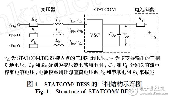
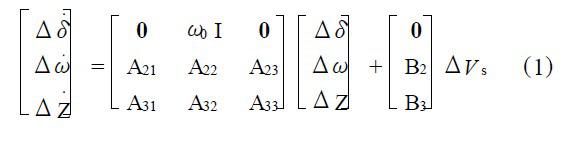
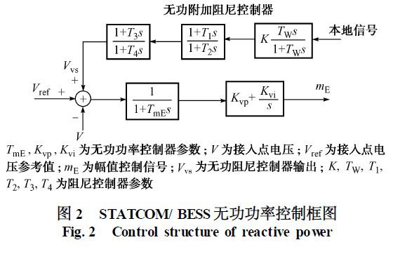
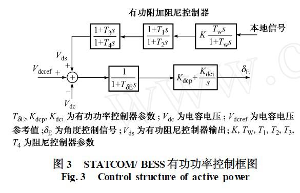
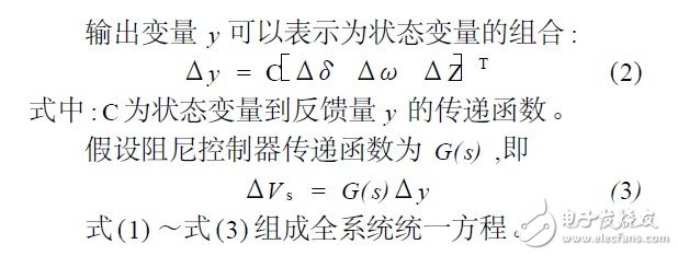
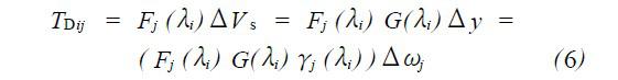
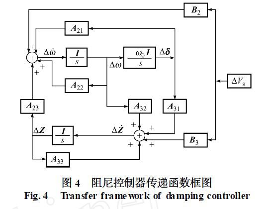
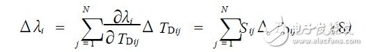
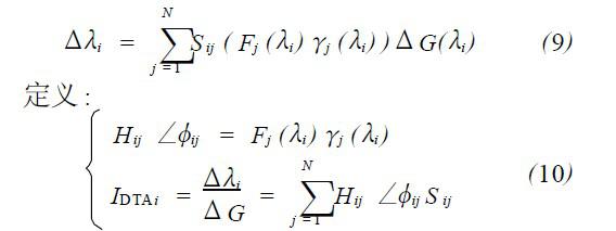
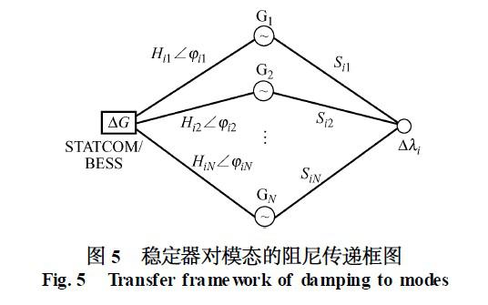
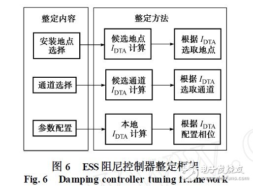
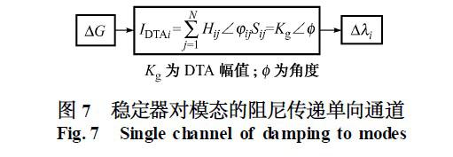
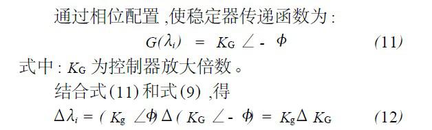
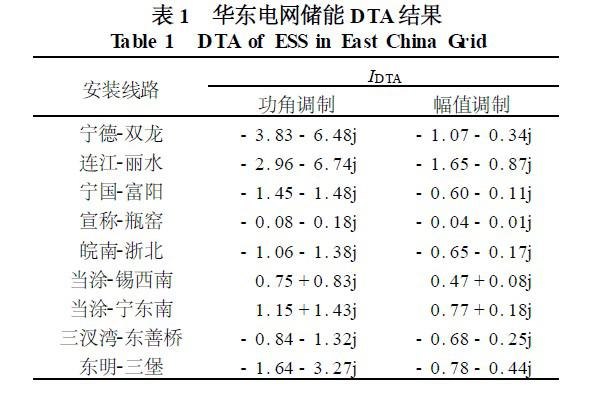
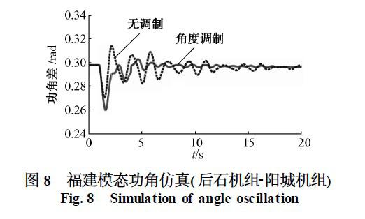
introduction The installation of an energy storage system (ESS) in the power system is a prerequisite for the large-scale utilization of renewable energy. The related application research of ESS is gradually developing internationally. ESS can adjust active and reactive power at the same time, thereby enhancing the stability of small disturbances in the power system. Research work has also been carried out at home and abroad. The literature has carried out research on the influence of various ESSs on system stability. Simulation and field test results show that ESS can provide positive damping to the system and can effectively improve the stability of the power system. The literature has conducted a preliminary discussion on the mechanism of ESS's suppression of low-frequency oscillations in power systems, but they have not proposed feasible methods for ESS parameter tuning. This article focuses on the mechanism and tuning methods. The damping torque analysis (DTA) method based on classical control theory is based on the actual concept of damping torque obtained by the motion of the generator rotor. The physical meaning is clear, and it has been practically applied to the power system stabilizer (PSS) to suppress the oscillation mechanism Of exploration. In this paper, the DTA method is used to study the mechanism of energy storage devices to suppress low-frequency oscillations. On this basis, a device tuning method based on DTA-based ESS positioning and stabilizer channel selection and parameter configuration is proposed. 1 Unified linearization model with energy storage A static reactive power compensator (STA TCOM) based on a voltage source inverter uses a battery as an energy storage element on the DC side to form a battery energy storage system (BESS), which forms STA TCOM/BESS [728], which can freely exchange active power with the system Power, its three-phase structure is shown in Figure 1. In the steady state process of the system, the capacitor voltage of the energy storage system remains unchanged, which is V dcref. In the system transient process, if the capacitor voltage drops (V dc STA TCOM/BESS contains active power controller and reactive power controller. The reactive power controller controls the voltage amplitude, and the active power controller controls the voltage phase angle. When used for low-frequency oscillation suppression, additional damping controllers can be designed on the two controllers respectively. The transfer function block diagram is shown in Figure 2 and Figure 3. The additional damping controller output signals V vs and V ds, as shown in Figure 2 and Figure 3, are collectively referred to as the control signal V s. The input signal of the damping controller is called the feedback signal y, that is, the local signal, which is generally taken as the power deviation value of the installed line. Linearize the energy storage system equation and integrate it with the entire system state equation. Through the interface of the network algebraic equation, the entire system linearization equation can be obtained: In the formula: δ is the power angle of the generator; ω is the speed; Z is the state variable of the generator in addition to the power angle and speed, and also includes the state variable of the energy storage device itself (not including the state variable of the additional damping controller); B is the transfer function of the stabilizer control signal V s to the state variable. 2 Energy storage system DTA 2. 1 DTA theory of energy storage system The basic concept of DTA is that the stable controller provides damping torque to the system. DTA can clearly reveal the information about the generation, distribution and transmission of the damping torque of the controller. Assuming there are N generators in the system, according to the whole system linearization equation (1), the transfer function block diagram is shown in Figure 4. The forward channel function from the control signal of the damping controller to the electromechanical oscillation link of the generator is: According to the linear control theory, the feedback signal y in equation (2) is a combination of state variables, which can be reconstructed separately by the speed ω of each generator, and γj (s) is the reconstruction function, which can be obtained: Δy = γj (s)Δωj j = 1 ,2, ..., N (5) The damping controller for the i-th oscillation mode, the torque provided to the j-th generator in the system is: Equation (6) shows that the stabilizer does not only provide damping torque to a certain generator, but to every generator. However, the torque provided by the stabilizer must pass through each generator to affect the oscillation mode, so it is necessary to consider the degree of influence of each generator on the mode. Define the sensitivity S ij of the i-th mode λi to the j-th generator torque TDij to evaluate the influence of the generator on the mode: Then the equation of the corresponding modal change due to the torque change provided by the damping controller is: From equation (6), the change of TDij can only be caused by the change of the damper transfer function, because the other parts are only related to the system. Get From equations (9) and (10), the damping transfer block diagram can be obtained (see Figure 5). It is found that the damping controller provides damping to the oscillation mode i through two sets of channels: first, through the first set of channels Hij ∠φij, to each station The unit provides damping torque, and then through the second group of channels Sij, through the participation of each unit in the oscillation mode, the damping of the mode is generated, and the damping torque is converted into the damping provided to the mode. Therefore, the DTA index IDTAi in Eq. (10) characterizes the influence ability of the controller on the modal, and clearly expresses the mechanism of the energy storage system stabilizer providing damping to the modal. 2.2 Tuning method of energy storage system based on DTA The energy storage system suppresses low-frequency oscillation, there are 3 settings that need to be considered, as shown in Figure 6. Since the DTA index characterizes the ability of energy storage to affect the modal, a large IDTA means that the energy storage has a large sensitivity to modal damping. Therefore, for the selection of the installation site, the IDTA is large as the selection criterion; the same can also be used as an installation channel Selection criteria. For parameter configuration, the phase compensation method can be extended to the phase setting of the stabilizer. The phase compensation method is proposed for the single-machine infinite power system, and for the energy storage system, damping is provided to the mode through N channels. Based on the IDTA index, the N channels are integrated, and the one-way channel shown in Figure 7 can be obtained. That is, after a reasonable angle configuration based on the DTA index, the change of KG directly affects the real part of the modal, but has no effect on the imaginary part. 3 Calculation example 3. 1 Two-zone four-machine system verification The network diagram of the two-zone four-machine system is shown in Appendix A, Figure A1. There is a weakly damped regional oscillation mode (frequency 0.563, damping 0.01), and the damping of this mode is improved by installing an energy storage system. For the selection of the controller modulation channel, Appendix A Table A1 is the analysis result when the energy storage system is installed in B7. the result shows: ①The stabilizer provides damping torque to all 4 generators, and the modal damping is affected by the 4 generators. The influence of the stabilizer on the modal is the sum of 4 channels; ②The effect of phase angle modulation is better than amplitude modulation This is consistent with the physical understanding of the energy storage system, because the phase angle modulation directly affects the active power. For the selection of the installation location of the device, Appendix A Table A2 is the analysis result of different installation locations during phase angle modulation, indicating that the effect of the energy storage system installed in B7 is better than that of B8, that is, the effect of installing the power outflow point is better. For the angle setting of the damping controller, the results obtained by using the setting method in section 2.2 are shown in Appendix A, Table A3. Based on the tuning parameters, the time-domain simulation diagrams are shown in Appendix A, Figure A2 and Figure A3, which verify the correctness of the tuning method. 3. 2 Promotion of actual power grid Take the 2010 summer high operation mode of East China Power Grid as an example to study the application of energy storage devices. There are 4 regional oscillation modes in this regional power grid in 2010, among which the Fu modeled state (frequency 0.567, damping 0.03) has the weakest damping. Therefore, the Fu modeled state is selected to study the suppression of the low-frequency oscillation of the modal by the energy storage system. For this mode, the first is the choice of the installation location. The typical regional tie line is selected as the alternative location, and the location with the greatest impact on the Fu modeling state is selected as the installation location of the energy storage device through the calculation of IDTA. The choice of the damping control channel is also based on the IDTA selection. The IDTA calculation results of the energy storage device installed on each tie line are shown in Table 1. Based on the comparison of IDTA installation locations, the Ningde-Shuanglong line was selected to install energy storage devices. The specific capacity is related to the line active power change limit. In the example, the maximum line active power change range does not exceed 35 MVA, so the capacity is 40 MVA. For channel selection, it is found that the phase angle modulation is better than the amplitude modulation, which is also consistent with the physical understanding. Through parameter setting, the simulation result is shown in Figure 8. Aiming at the blessing modeling state of the East China power grid in 2010, by installing energy storage devices and phase angle modulation on the Ningde-Shuanglong line, the blessing modeling state can be effectively suppressed. 4 Conclusion In this paper, DTA is used to study the mechanism of energy storage devices suppressing low-frequency oscillations, and clearly expresses the entire process of energy storage devices providing damping to the modal. On this basis, a method of positioning and parameter configuration of energy storage components based on DTA is proposed. The installation effect of the power outflow end of the line is obvious, and the phase angle modulation is better than the amplitude modulation. The actual power grid shows that energy storage has a good application prospect for improving the stability of low-frequency oscillations in large-scale power grids. The application of energy storage devices is closely related to the capacity. How to take the capacity factor into account in the DTA tuning method, how to select the appropriate capacity to face various oscillation scenarios and improve the robustness of the energy storage device, this is an energy storage device The key issue of whether it can be applied on a large scale is also a significant research direction. Water Purifier Pressure Sensor Shenzhen Ever-smart Sensor Technology Co., LTD , https://www.fluhandy.com