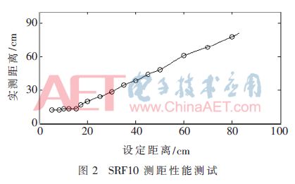
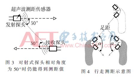
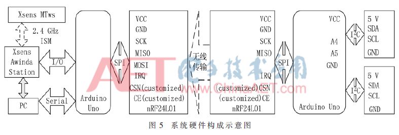
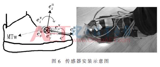
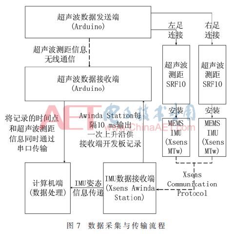
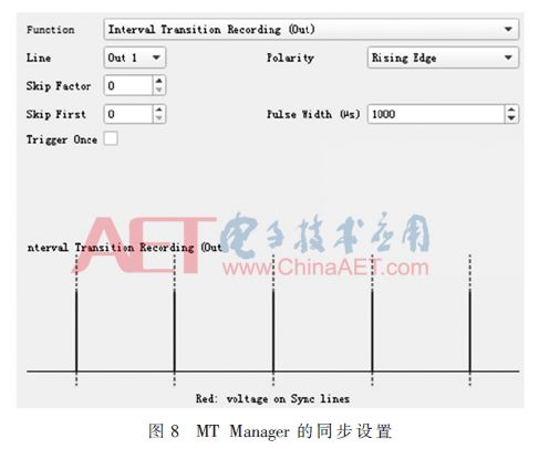
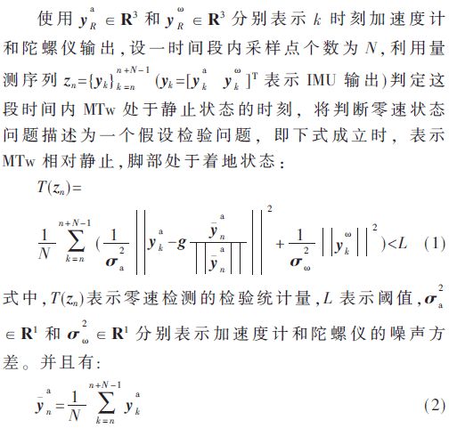
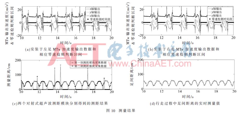
Summary: Aiming at the application requirements of high-precision pedestrian indoor autonomous navigation and positioning, a wearable human motion measurement device prototype integrating Arduino and Xsens Awinda inertial measurement kit was designed. The system is easy to wear and has high reliability. It realizes the simultaneous measurement of biped IMU information and the distance between the feet, and supports wireless transmission, remote storage and analysis of data. The distance between the feet is continuously collected by the modified dual SRF10 ultrasonic ranging module, and combined with the biped inertial measurement data, the zero-speed detection algorithm is used to obtain the walking gait law, which helps to improve the accuracy of pedestrian inertial navigation and positioning. 0 Preface At present, autonomous navigation technology mainly relies on gait parameters in space and time, combined with biological characteristics for motion estimation and navigation positioning. One idea is to use sensors to measure the movement information of the target part, estimate the movement characteristics by analyzing the signal characteristics of the person walking, determine the step frequency and stride length, and combine with the heading measurement system to obtain the movement trajectory. The shortcoming lies in the actual walking process. Changing conditions are difficult to maintain a consistently high signal recognition rate. Another idea is to detect the zero-velocity state when the foot is on the ground, and use the zero-velocity value as the Kalman filter observation value to correct the inertial navigation solution error. When a person is walking, the time for the feet to touch the ground is short, so the auxiliary effect is limited. Moreover, the zero-speed state detection method has a limited effect on the correction of the gyroscope output error, and will cause a large deviation of the walking trajectory over time. The distance between feet is a useful navigation aid. At present, the research work of this idea is mainly divided into three directions: (1) Calibrate the zero offset of the two gyros by tracking the distance of the two feet, thereby restraining the azimuth drift, in which the distance between the feet is determined using an ultrasonic transceiver [1]; (2) ) Set the distance threshold constraint between the feet in the algorithm to reduce the heading error [2-4]; (3) Use the idea of ​​single-shot and multiple-receive, arrange multiple ultrasonic transceivers on both feet, and pass receivers in different positions The time difference of the step yields the displacement information and posture information of the footsteps [5]. Based on this idea, this article designs a prototype of a wearable human motion measurement device based on the Arduino development platform and Xsens Awinda MTw inertial sensor, which realizes continuous and synchronous measurement of inertial information and distance information between feet. 1 System principle A MEMS Inertial Mesurement Unit (MEMS IMU) is used to measure the inertial data of the installation position during the movement of the feet. The system platform design goal meets four key points: (1) Real-time measurement of the distance between the feet under actual gait conditions, requiring accurate and stable data, and sensitive data feedback; (2) Synchronous collection of measurement information from each sensor; (3) Automatic storage And processing data; (4) The equipment is portable and easy to use, and is convenient to wear. The hardware collocation idea of ​​this system is shown in Fig. 1. Two ultrasonic ranging modules are used to measure the distance between the feet at any relative position. The ultrasonic data transmitter is responsible for ranging, and the data is wirelessly transmitted to the ultrasonic data receiver at regular intervals. On the other hand, the bipedal inertial motion information is synchronously collected by the central control unit and transmitted to the computer. The computer terminal combines the control sequence to obtain the synchronous measurement information of each sensor. 2 System hardware design 2.1 Xsens MTw Awinda kit MT Manager is an interactive control interface with MTW Awinda, using the built-in Message Terminal (Device Message Terminal) to monitor inertial sensor information, you can set the wireless update rate of MTW and the synchronization signal trigger mode of Awinda Station. From a large amount of literature, most of the pedestrian navigation and positioning studies based on MEMS IMU use Xsens inertial motion sensors as the measurement platform. 2.2 Ranging control board This device uses two Arduino development boards as the core control module. One is used as the ultrasonic data measurement and transmission terminal, responsible for the collection and transmission of ultrasonic data, and it is carried with you. The other is used as an ultrasonic data receiver, which is synchronized with Awinda Station. 2.3 Ranging module In response to the requirements of the inter-foot distance measurement scene, this device adopts the ultrasonic distance measurement method for measurement. Devantech SRF10 ranging from 3 cm to 6 m, accuracy 1 cm, with filtering and noise reduction function, probe beam angle 72°, including 400ST100 transmitting probe, 400SR100 receiving probe and control circuit 3 main parts, data communication through I2C protocol . Different I2C addresses must be configured for SRF10 connected to the same I2C bus. Pay attention to the I2C address conversion between Arduino and SRF10. The ranging range and analog gain can be modified through the SRF10 register, and appropriate parameters can reduce measurement errors. The greater the gain adjustment, the greater the sensitivity to receive weak echoes. In order to adapt to the real-time measurement of the step distance under normal gait conditions, the connection between the SRF10 transmitting probe and the control chip is extended and transformed into a through-beam ultrasonic module. Using laser ranging to calibrate the measurement error, the relationship between the measured distance and the real distance is shown in Figure 2. When the real distance is less than 20 cm, the deviation of the measured value is large. The directivity test of the ultrasonic ranging module is shown in Figure 3. The modified SRF10 can obtain better ranging results when the relative angle between the transceiver probes is within 50°. The two modified distance measuring modules are separated by a certain angle during installation. The distance measuring diagram is shown in Figure 4, and the angle between the probes of the distance measuring module is α. Perform multiple pre-tests. When the step range is 10 cm to 100 cm, the angle α is adjusted to 60° to 100° to ensure normal data collection when walking. In this system platform, the included angle α is set to 90°. Both SCL and SDA in the I2C bus are clamped at a high level with a 1.8 kΩ pull-up resistor. The SCL and SDA pins of SRF10 are connected to Arduino analog pins A5 and A4 respectively, and the two SRF10s are connected in parallel to serve as an I2C bus. The slave. When the module sends ultrasonic collection data, the SDA of I2C is pulled high to ensure data transmission. When the ranging result is obtained, SRF10 responds to the I2C bus again. This is very important for determining the system delay and achieving synchronization. 2.4 Wireless transmission module nRF24L01 is a GFSK single-chip radio frequency transceiver chip. The working frequency band is 2.4~2.5 GHz ISM. The channel and setting protocol are selected through the SPI interface. The SPI interface works in master-slave mode, full-duplex mode, and transmits wireless data with synchronous clock beats, serial The relative positions of the signal symbols in the data stream are fixed. After power-on, configure the module through the CE interface. The device uses the enhanced ShockBurstTM mode to control the data response and retransmission functions. The two nRF24L01 are respectively used as the transmitter and receiver. The two sets of ranging information collected in each cycle are transmitted remotely at the same time. The actual size of the data is 8 B. 2.5 Hardware transformation and matching of target equipment The system hardware structure diagram is shown as in Fig. 5. This device uses TI TXS0108E bidirectional level conversion chip to ensure normal communication between modules, and its maximum data rate is 110 Mb/s (push-pull), 1.2 Mb/s (open drain). The chip A port tracks the power supply voltage of the VCCA pin and connects to the 3.3 V voltage value pin. Port B tracks the power supply voltage of the VCCB pin and connects to the 5 V voltage value pin. The output enable OE pin inputs a high level. The hardware structure is divided into data acquisition, receiving and processing parts. The modified through-beam SRF10 ultrasonic ranging module transceiver probes are installed on different Xsens MTws. The connection between the probes bypasses the torso and is fixed by magic buckles. The Xsens MTw is placed on the upper. The self-designed mounting assembly has the function of adjusting the angle between the transmitting and receiving probes. The coordinate system of MTw and the installation of equipment are shown in Figure 6. 3 Data collection and processing flow The main workflow of the system is: equipment wearing and installation, target movement and data collection, data wireless transmission, data fusion, data storage and processing. Figure 7 shows the equipment data collection and transmission process. The collected motion data is wirelessly transmitted to the ultrasonic data receiving end and the IMU data receiving end, and the computer simultaneously receives the ultrasonic ranging information with time stamp and the IMU inertial motion parameter information for synchronization processing and data calculation. Figure 8 shows the MT Manager synchronization signal trigger mode setting. Awinda Station sends a rising edge synchronization signal to the outside through Sync Out Line1. The sending cycle is 10 ms, which is the same as the IMU data update cycle, and the signal pulse width is 1 ms. Awinda Station starts data collection and calculation when the command is given to start recording, and uses the Interval Transition Recording synchronization method to ensure that the system clock of the Awinda Station during data recording is accurately obtained. On the one hand, the ultrasonic data receiving end Arduino uses an internal interrupt to count the rising edge signal of the synchronous output of each frame of Awinda Station, to achieve precise synchronization of the acquisition time, with a synchronization accuracy of 1 ms. Once two ultrasonic ranging data are received, the ranging value and the counting result at the moment are output at the same time to obtain the original data. The Arduino program flow chart of the ultrasonic data receiver is shown in Figure 9. The inertial data update frequency of the two MTw wireless inertial sensors is 100 Hz. On the other hand, Awinda Station outputs the collected inertial data to the computer, and the file contains the output of each sensor of MTw (Sensor Component Readout). SRF10 collects full distance data in ms, and converts it into distance measurement values ​​during data processing. Since two SRF10s can cause interference when ranging at the same time, the ranging time interval is set to 20 ms. When each ranging is completed, the sending end transmits two ranging data to the receiving end at the same time. The SRF10 ranging period and ultrasonic data are sent The period is 50 ms. For the selection of ultrasonic ranging frequency, consider the following points: (1) When an ordinary person walks at a normal speed, a complete gait cycle is about 1.2 s~1.8 s, and the time of any one foot off the ground is about 31.8%[6]; (2) Based on the stride length of people in various sports (such as walking, running, etc.), the distance measurement range of the module is set to 2 m, and the distance measurement module needs about 5.8 ms to process data, so SRF10 ultrasonic The period of ranging data collection cannot be less than this length of time. Adjust the analog gain to match the module's detection frequency and ranging range parameters; (3) The output frequency of the ultrasonic ranging module and the output frequency of the Awinda Station are set to an integer multiple to make the data Pass the match. At the ultrasonic data sending end, SRF10 needs to delay a period of time after acquiring the data (set to 20 ms in the program) to read the measurement data from the register, and use the oscilloscope to detect the pulse signal and ultrasonic data reception when the ultrasonic probe starts working. The Arduino receives the pulse signal of the data, and it takes a total of 21.5 ms to get the average time of the device data transmission process. The extra 1.5 ms is mainly the time spent in the wireless transmission process. Based on the data to determine the specific start and ranging time of the SRF10, The ranging data is combined with the IMU data to complete synchronous collection. The equipment synchronization process is based on the internal clock of Awinda Station, and the ultrasonic ranging period can be adjusted to 30 ms at the fastest. 4 Equipment data collection and processing Use two SRF10s to measure the real-time foot distance of the human body under normal gait conditions. Due to the beam angle of the ultrasonic probe, for the installation method of the device module, two measurement values ​​can be obtained at the same time, which need to be determined within one gait cycle Relatively accurate measurement value. The idea is to combine the inertial motion parameters collected by Xsens MTw, and apply the Zero-Velocity Detection algorithm (Zero-Velocity Detection) [7] to obtain the time period during which the feet remain relatively stationary on the ground, thereby obtaining the law of step motion. Use the above zero-speed detection algorithm to use this wearable device for data collection test, walk along a straight line at a constant speed (about 5 km/h), select the data time length 10 s, and measure the human body motion data result as shown in Figure 10. Figures 10(a) and 10(b) respectively show the three-axis output of the accelerometer measured by the MTw of the left foot and the MTw of the right foot, and the state of the foot in the landing phase determined by the zero-speed detection algorithm. Periodic gait such as touching the ground, landing, raising the foot, and swinging. Figure 10(c) shows the distance measurement values ​​obtained by two ultrasonic distance measurement modules. Due to the characteristics of sound wave reflection distance measurement, there are some outliers in the actual measurement value. The ranging results of the two modules are selected and processed according to the gait information in the following manner: (1) Judging the direction of each step according to the output of the inertial sensor; (2) Taking the walking direction as an example, under normal circumstances, one The foot is located diagonally in front of the other foot at the moment of just touching the ground. According to the aforementioned module installation conditions, select the distance measurement value of the module that meets the angle measurement position at this time; (3) Take the above operations for each step, combining the feet The relative position change law finally obtains the real-time measurement value of the distance between the feet, and at the same time, removes some outliers, and the final measurement result is shown in Figure 10(d). 5 Conclusion The system integrates inertial measurement unit and ultrasonic distance measurement sensor to directly measure the distance between the feet during pedestrian movement in real time, and realize the synchronous collection of pedestrian navigation data, and promote the research work using step distance as a new constraint condition for pedestrian navigation. The wireless communication module realizes the remote storage and processing of data. It is not necessary to carry the computing terminal with you. It is lighter to wear, and the data collection is stable and reliable, which meets the requirements of wearable body motion measurement. Based on this hardware platform, further work includes: (1) For multiple gait situations, more ultrasonic ranging transceiver modules are used to measure foot distance under more complex angles; (2) The overall platform tends to be modularized for perfect navigation The shoe function provides ideas, and the data processing part can be transplanted to other equipment terminals according to actual use requirements.
V.35 CONNECTORS
SPECIFICATIONS V.35 CONNECTORS ShenZhen Antenk Electronics Co,Ltd , https://www.pcbsocket.com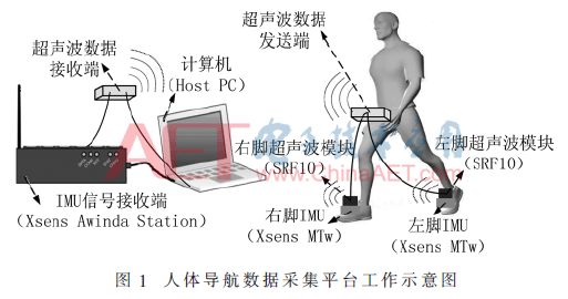


Current Rating :7A
Insulation Resistance :≥1000 MΩ
Dielectric Withstanding Voatge :
1200VAC MIN 1Minute
Operating temperature : -55°C~ 105°C
Contact Resistance :≤35mΩ
Insulator Material :PBT & G/F UL 94V-0
Contact Material : Phosphor Bronze
Suitable:V.35VCT-F FEMALE TERMINAL